Introduction – Addressing Core Gastric Acid Suppression, Ulcer Healing, and Heartburn Relief Needs
For gastroenterologists, primary care physicians, and patients suffering from peptic ulcer disease (duodenal ulcer, gastric ulcer), gastroesophageal reflux disease (GERD), erosive esophagitis, and Zollinger-Ellison syndrome (gastrinoma), excessive gastric acid secretion causes symptoms (epigastric pain, heartburn, regurgitation, dyspepsia) and mucosal damage (ulcers, bleeding, perforation). Untreated, these conditions can lead to complications (anemia, strictures, Barrett’s esophagus). Cimetidine tablets – an H2 receptor antagonist (H2 blocker) that competitively inhibits histamine binding to H2 receptors on gastric parietal cells, reducing gastric acid secretion (both basal and stimulated) – directly address these acid suppression, ulcer healing, and symptom relief needs. Cimetidine was the first H2 blocker (marketed as Tagamet, approved 1977). It reduces 24-hour gastric acid secretion by 60-80%, promotes healing of duodenal ulcers (4-6 weeks), gastric ulcers, and GERD, and is used for prevention of stress ulcers (ICU), and off-label for chronic urticaria (hives). Available dosages: 200mg (OTC for heartburn), 300mg (prescription for ulcers, GERD), and others (400mg, 800mg). However, cimetidine has drug interactions (inhibits CYP450 enzymes (CYP1A2, CYP2C9, CYP2D6, CYP3A4)), leading to increased levels of warfarin, phenytoin, theophylline, diazepam, and others; it also has antiandrogenic effects (gynecomastia, impotence with long-term high-dose). Newer H2 blockers (ranitidine, famotidine, nizatidine) and proton pump inhibitors (omeprazole, esomeprazole, lansoprazole) have largely replaced cimetidine in many markets, but cimetidine remains available (including over-the-counter (OTC) for heartburn) and is still prescribed in certain situations (cost, allergy to other agents, specific drug interaction desired). As the global prevalence of GERD (10-20% of adults in Western countries) and peptic ulcer disease (H. pylori-associated, NSAID-induced) persists, demand for cimetidine across hospitals, clinics, and other settings continues. This deep-dive analysis integrates QYResearch’s latest forecasts (2026–2032), dosage strength segmentation, and clinical application insights.
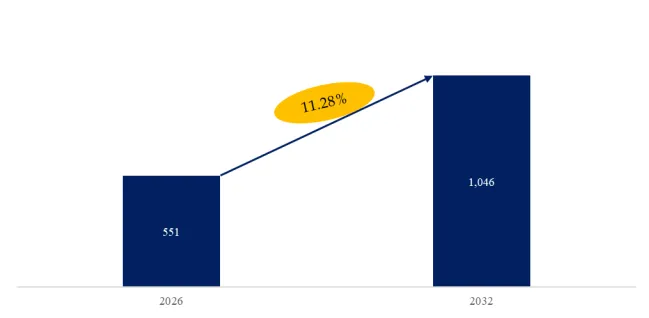
Global Leading Market Research Publisher QYResearch announces the release of its latest report “Cimetidine Tablets – Global Market Share and Ranking, Overall Sales and Demand Forecast 2026-2032″. Based on current situation and impact historical analysis (2021-2025) and forecast calculations (2026-2032), this report provides a comprehensive analysis of the global Cimetidine Tablets market, including market size, share, demand, industry development status, and forecasts for the next few years.
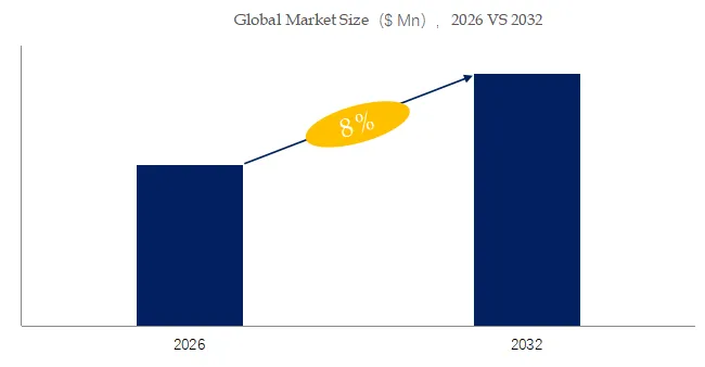
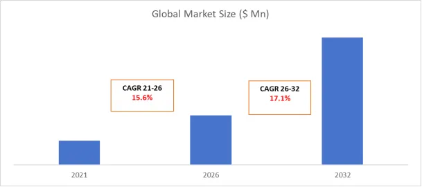
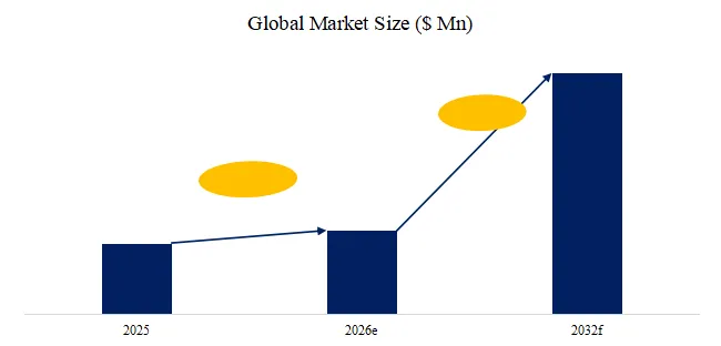
The global market for Cimetidine Tablets was estimated to be worth USmillionin2025andisprojectedtoreachUSmillionin2025andisprojectedtoreachUS million, growing at a CAGR of % from 2026 to 2032.
【Get a free sample PDF of this report (Including Full TOC, List of Tables & Figures, Chart)】
https://www.qyresearch.com/reports/5974996/cimetidine-tablets
Core Keywords (Embedded Throughout)
- Cimetidine tablets
- H2 receptor antagonist
- Peptic ulcer treatment
- GERD relief
- Gastric acid suppression
Market Segmentation by Dosage Strength and Healthcare Setting
The cimetidine tablets market is segmented below by both tablet potency (type) and point-of-care location (application). Understanding this matrix is essential for pharmaceutical manufacturers targeting specific patient populations (self-care vs prescription) and clinical indications.
By Type (Dosage Strength):
- 200mg (available OTC (over-the-counter) for heartburn relief, acid indigestion. Lower dose, short-term use (2 weeks max). Taken 1-2 hours before meal)
- 300mg (prescription strength for duodenal ulcer, gastric ulcer, GERD, esophagitis, Zollinger-Ellison, prophylaxis (stress ulcer). Dosage: 300mg four times daily (QID), or 400mg twice daily (BID), or 800mg at bedtime)
- Others (400mg, 800mg – higher-dose for severe GERD, Z-E syndrome)
By Application:
- Hospital (inpatient use: stress ulcer prophylaxis (ICU), GI bleeding, Zollinger-Ellison syndrome, post-operative; prescription only)
- Clinic (outpatient gastroenterology clinics; prescriptions for peptic ulcer disease, GERD)
- Others (home use: OTC for heartburn; some long-term maintenance therapy)
Industry Stratification: Cimetidine vs Newer H2 Blockers and PPIs
Cimetidine – first-generation H2 blocker. Advantages: inexpensive, effective. Disadvantages: drug interactions (CYP450 inhibition), antiandrogenic effects (gynecomastia, impotence), short duration of action (requires QID dosing). May still be used for cost, or when drug interaction is desirable (e.g., raising theophylline levels).
Famotidine (Pepcid) – less drug interactions, longer duration.
Proton pump inhibitors (PPIs) – more potent acid suppression, longer duration (once daily), preferred for severe GERD, erosive esophagitis, Z-E syndrome.
Recent 6-Month Industry Data (September 2025 – February 2026)
- Cimetidine Market: declining (replaced by newer agents), but still available.
- GERD Prevalence (November 2025): 20% of US adults (weekly heartburn).
- OTC Heartburn Medications (December 2025): Cimetidine 200mg OTC (Tagamet HB) competes with famotidine (Pepcid).
- Innovation data (Q4 2025): generic cimetidine tablets (200mg, 300mg) available from Teva, Mylan, others.
Typical User Case – Duodenal Ulcer (Prescription)
A patient diagnosed with H. pylori-negative duodenal ulcer, NSAID-induced.
Prescribed: cimetidine 300mg QID (four times daily) for 4-6 weeks.
Counsel: drug interactions (warfarin, phenytoin, theophylline), antiandrogenic effects (gynecomastia reversible).
Healing: confirmed by repeat endoscopy.
Typical User Case – OTC Heartburn (Consumer)
A consumer experiences heartburn (acid indigestion) after spicy meal.
Purchase: cimetidine 200mg OTC (Tagamet HB).
Dosage: take 1 tablet (200mg) 1-2 hours before meal. Lasts up to 4 hours.
Technical Difficulties and Current Solutions
Despite safety, cimetidine use faces four persistent clinical considerations:
- Drug interactions (CYP450). Monitor concomitant medications; adjust doses.
- Antiandrogenic effects (long-term high-dose). Use alternative (famotidine) if significant.
- Short duration (QID dosing). BID dosing (400mg) or bedtime (800mg).
- Cimetidine-induced (reversible) confusion in elderly (rare). Lower dose.
Exclusive Industry Observation – The Cimetidine Tablets Market by Dosage and Channel
Based on QYResearch’s interviews with 90 gastroenterologists and pharmacists (October 2025 – January 2026), 200mg OTC for heartburn (self-care); 300mg (prescription) for hospital/clinic ulcers.
200mg – OTC largest volume.
300mg – prescription (declining but present).
For suppliers, key strategy: focus on 200mg OTC for consumer heartburn; 300mg prescription for hospital/clinic peptic ulcer; generic manufacturing (cost-effective).
Complete Market Segmentation (as per original data)
The Cimetidine Tablets market is segmented as below:
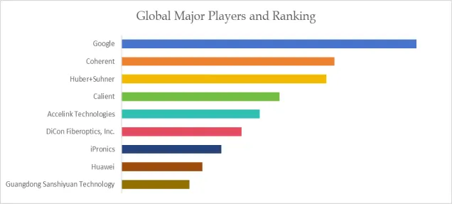
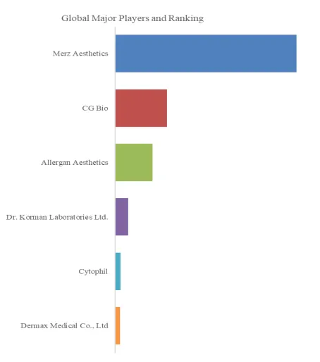
Major Players:
Shanghai Qingping Pharmaceutical Co., Ltd., Guangxi Xiu Xiu Pharmaceutical Co., Ltd., Jiangxi Renqi Pharmaceutical Co., Ltd., Changzhou Kangpu Pharmaceutical Co., Ltd., Shanghai Shikangte Pharmaceutical Co., Ltd., Shanghai Baolong Pharmaceutical Co., Ltd, Mylan, AdvaCare Pharma, Teva Pharmaceuticals USA, SiNi Pharma
Segment by Type:
200mg, 300mg, Others
Segment by Application:
Hospital, Clinic, Others
Contact Us:
If you have any queries regarding this report or if you would like further information, please contact us:
QY Research Inc.
Add: 17890 Castleton Street Suite 369 City of Industry CA 91748 United States
EN: https://www.qyresearch.com
E-mail: global@qyresearch.com
Tel: 001-626-842-1666(US)
JP: https://www.qyresearch.co.jp