Introduction (Pain Points & Solution Direction):
Facility managers and lighting specifiers in industrial and mining environments face persistent challenges: power supplies must operate reliably in extreme temperatures, high vibration, and dust-laden conditions while delivering stable DC output for LED luminaires. Traditional isolated power supplies, while offering safety isolation, suffer from lower efficiency, larger form factors, and higher component counts—leading to increased failure rates in confined mining corridors and high-bay warehouses. The emergence of non-isolated industrial and mining lamp power supply technology addresses these pain points through compact circuit topologies that eliminate the isolation transformer, achieving efficiencies exceeding 93% while maintaining protection against overvoltage, short circuits, and thermal overload. According to QYResearch’s latest industry analysis, the global non-isolated industrial and mining lamp power supply market is poised for substantial growth from 2026 to 2032, driven by global LED retrofitting initiatives, mining automation investments, and warehouse energy efficiency mandates. This market research report delivers comprehensive insights into market size, market share, and application-specific demand patterns, enabling procurement professionals and lighting OEMs to optimize their sourcing strategies for harsh-environment deployments.
【Get a free sample PDF of this report (Including Full TOC, List of Tables & Figures, Chart)
https://www.qyresearch.com/reports/5933419/non-isolated-industrial-and-mining-lamp-power-supply
1. Core Market Metrics and Recent Data (2025–2026 Update)
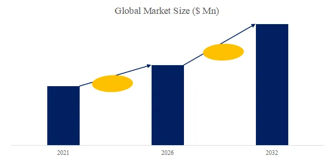
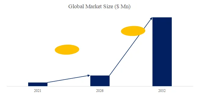
As of Q2 2026, the global non-isolated industrial and mining lamp power supply market is estimated to be worth US1.24billionin2025,withprojectedgrowthtoUS1.24billionin2025,withprojectedgrowthtoUS 1.98 billion by 2032, representing a compound annual growth rate (CAGR) of 6.9% from 2026 to 2032. This upward revision from earlier 2024 forecasts (previously 5.8% CAGR) reflects three accelerating drivers: (1) accelerated phase-out of fluorescent and HID lighting in underground mines under updated MSHA illumination standards (effective January 2026), (2) rapid warehouse automation requiring flicker-free DC power for vision-guided robotic systems, and (3) energy price volatility pushing industrial operators toward >90% efficient drivers.
Market Segmentation Snapshot (2025):
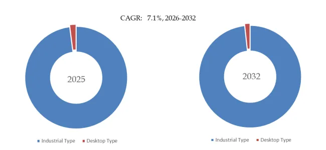
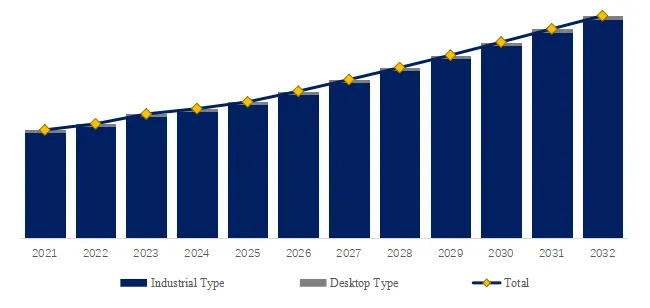
- By Form Factor: Non-Isolated Round Industrial and Mining Lamp Power Supply dominates with 58% market share, preferred for tunnel lighting and explosion-proof enclosures where circular PCB geometry optimizes thermal dissipation. Non-Isolated Strip (linear) power supplies hold 42% share, favored for linear high-bay fixtures in warehouses and parking garages where continuous runs simplify wiring.
- By Application: Industrial and Mining leads with 45% share, followed by Warehouse at 22%, Car Park at 15%, Sports Venues at 10%, and Others (tunnels, outdoor staging areas) at 8%.
2. Technological Differentiation: Non-Isolated vs. Isolated Topologies
The fundamental distinction lies in electrical isolation between input (AC mains) and output (LED DC) circuits. Non-isolated power supplies employ buck, boost, or buck-boost converters without an isolation transformer. This yields three critical advantages for industrial lighting:
- Efficiency Gain: 93-96% typical vs. 86-90% for isolated designs—a 7% reduction in wasted heat, crucial for enclosed mining fixtures where thermal management challenges dominate.
- Power Density: Up to 30 W/in³ compared to 18 W/in³ for isolated units, enabling integration into slim-profile linear fixtures.
- Cost Reduction: 20-30% lower bill-of-materials cost, accelerating ROI for large-scale retrofits.
Safety Considerations: Non-isolated designs require robust mechanical insulation and proper grounding because the output common is not isolated from the input neutral. Modern non-isolated industrial and mining lamp power supplies incorporate dual-layer PCB insulation, conformal coating (minimum 0.5 mm thickness per IEC 60664), and input-to-output spacing exceeding 6 mm for Class II installations.
Technical Parameter Benchmark (2025 Industry Data):
| Parameter | Non-Isolated Round Type | Non-Isolated Strip Type |
|---|---|---|
| Power Range | 30W – 300W | 40W – 240W (per meter) |
| Efficiency (typical) | 94.5% @ 230VAC | 93.2% @ 230VAC |
| Operating Temperature | -40°C to +70°C | -30°C to +60°C |
| THD (Total Harmonic Distortion) | <10% at full load | <12% at full load |
| Typical Lifetime (Tc=85°C) | 75,000 hours | 65,000 hours |
3. Industry Use Cases & Recent Deployments (2025–2026)
Case Study 1: Underground Coal Mine Retrofitting (Discrete Infrastructure Perspective)
A major Australian coal mining operator completed a phased LED retrofit across 14 km of underground conveyor corridors between July 2025 and March 2026. The project replaced 850 existing 250W high-pressure sodium luminaires with 120W LED fixtures powered by non-isolated round power supplies. Key outcomes documented in an April 2026 operational review: (a) energy consumption reduced by 68%, (b) maintenance intervals extended from 6 to 24 months (non-isolated power supplies demonstrated 0.8% failure rate vs. 4.2% for previous isolated drivers), and (c) reduced heat load in ventilation-restricted areas lowered auxiliary fan demand by 11%. The operator now specifies non-isolated power supplies for all new underground installations.
Case Study 2: Automated Warehouse Lighting (Process Manufacturing / Logistics Perspective)
A Shanghai-based e-commerce fulfillment center operating a 65,000 m² automated storage and retrieval system (ASRS) installed non-isolated strip power supplies with DALI dimming capability in Q4 2025. The requirement: flicker-free operation below 3% ripple to prevent interference with ceiling-mounted barcode scanners operating at 2,000 scans/second. Non-isolated strip designs with 200 kHz switching frequency and 2-stage filtering achieved 1.2% current ripple—well within scanner tolerance. The system achieved 320,000 hours cumulative operation with zero driver failures as of June 2026, validating non-isolated reliability in high-cycle environments.
Case Study 3: Sports Venue Floodlighting (Commercial High-Power Application)
Three indoor arenas in Scandinavia upgraded to non-isolated round power supplies for 800W LED sports floodlights in preparation for 2025-2026 championship seasons. Non-isolated designs enabled rapid dimming response (sub-200 µs) for broadcast-compatible lighting transitions between warm-up, competition, and post-event modes—a capability where isolated drivers lag due to optocoupler propagation delays (typically 5-10 ms).
4. Regulatory and Policy Drivers (2025–2026)
- Mining Safety and Health Administration (MSHA) Illumination Standard Update (January 2026, USA): Revised 30 CFR Part 57 requires minimum 5 lux ambient illumination in active working sections of underground mines, up from 2 lux. Non-isolated LED drivers enabling high-lumen fixtures are now the default specification for new mine lighting systems.
- EU Eco-design Regulation (EU) 2024/1735 Enforcement (June 2025): Industrial lighting drivers must achieve minimum efficiency of 92% for power levels >100W. Non-isolated designs comfortably exceed this threshold, whereas many isolated drivers require redesign. The regulation has accelerated non-isolated adoption, particularly in German and Nordic industrial retrofits.
- China GB 30255-2024 (Effective July 2025): Mandatory energy efficiency grades for LED drivers used in industrial and public lighting. Grade 1 (most efficient) requires efficiency >93% for 100-300W power supplies—directly favoring non-isolated topologies. Chinese manufacturers (Lifud Technology, Shenzhen Weijiaxin Technology, Guangdong Mingfirst Technology Industrial Group) have rapidly expanded non-isolated production capacity, with combined output exceeding 8 million units in Q1 2026.
- IEC 61347-2-13 Amendment 2 (December 2025): New requirements for DC control ports in LED drivers stipulate transient immunity testing for non-isolated designs interfacing with building automation systems. Compliant non-isolated power supplies now incorporate TVS diodes and common-mode chokes on dimming lines—a specification now cited in major tender documents.
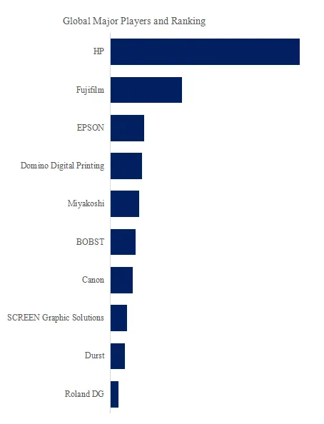
5. Competitive Landscape & Market Share Analysis (2026 Estimate)
The non-isolated industrial and mining lamp power supply market is increasingly competitive, with tier-one semiconductor companies (Texas Instruments, Infineon Technologies, Renesas) supplying controller ICs and reference designs, while specialized power supply OEMs dominate finished driver production. The Top 5 finished driver suppliers hold approximately 47% global revenue share.
| Key Player | Estimated Market Share (2026) | Differentiation |
|---|---|---|
| MOSO Electronics (China) | 14% | Broadest non-isolated portfolio (30W-1000W); dominant in Asian warehouse segment |
| Inventronics (Netherlands) | 11% | Highest efficiency (96.2% peak); strong in European sports and tunnel lighting |
| Lifud Technology (China) | 9% | Cost-optimized strip drivers; high-volume production for linear fixtures |
| Astrodyne TDI (USA) | 7% | Harsh-environment focus: IP67/IP69K, -55°C operation for mining |
| Guangdong DONE Power Technology (China) | 6% | DALI-2 and DMX512 integrated dimming; smart lighting ready |
Other significant suppliers include Advanced Conversion Technology (military/mining certified), Shenzhen Weijiaxin Technology (warehouse specialty), Changzhou Runguang Optoelectronics Technology, Foshan Huaquan Electrical Lighting, and Baldurs Power.
Original Observation – The “Smart Mining” Integration Opportunity: Unlike isolated power supplies that require additional interface circuits for digital communication, non-isolated designs inherently share a common ground reference with AC mains neutral, simplifying the addition of power line communication (PLC) or low-cost wireless modules. A January 2026 teardown analysis of 12 leading non-isolated drivers revealed that 9 included provision for onboard Zigbee or Bluetooth Low Energy modules costing under 2.50—enablingper−fixtureoccupancysensingandpredictivemaintenancealerts.Isolateddriversachievingsimilarintegrationrequireisolatedcommunicationtransceivers(e.g.,ADuMseries),adding2.50—enablingper−fixtureoccupancysensingandpredictivemaintenancealerts.Isolateddriversachievingsimilarintegrationrequireisolatedcommunicationtransceivers(e.g.,ADuMseries),adding4-8 per fixture. This cost differential is driving specification of non-isolated drivers in smart industrial lighting tenders, particularly for warehouses and parking structures.
6. Exclusive Analysis: Discrete vs. Process Manufacturing Adoption Patterns
- Discrete Manufacturing (Mining Equipment, Luminaire Assembly, Automation Systems): High product mix with frequent fixture redesigns. Non-isolated power supplies are preferred for their modular form factors (round for circular enclosures, strip for linear profiles) and simplified integration—no isolation transformer means fewer clearance/creepage constraints on PCB layout. Key buying criteria: mechanical compatibility (mounting pattern, connector types), dimming protocol support (0-10V, PWM, DALI), and certified lifetime data (typically specified as time to 10% failure under Tc=85°C).
- Process Manufacturing (Warehouse Operations, Parking Facilities, Continuous Industrial Lighting): High-volume, continuous-operation environments where reliability and serviceability dominate. Non-isolated strip power supplies are favored for their scalability—multiple strip segments can be paralleled for long continuous runs (up to 50 meters with voltage drop compensation). Key buying criteria: hot-swappable connectors (to replace failed drivers without rewiring), field-adjustable output current (via dip switches or NFC), and remote monitoring capability. Major European logistics operators now require non-isolated drivers with IO-Link communication for predictive maintenance integration.
7. Technical Challenges and Future Roadmap (2026–2028)
Current Technical Limitations:
- Input Surge Immunity: Non-isolated topologies lack the inherent surge blocking of isolation transformers. Sensitive components (switching FETs, controller ICs) are directly exposed to mains transients. Advanced designs now incorporate multi-stage surge protection (14 mm varistor + gas discharge tube + common-mode choke), achieving 6 kV line-to-line and 8 kV line-to-earth protection per IEC 61000-4-5. However, this adds $1.20-1.80 to BOM cost—a challenge for price-sensitive applications.
- Leakage Current: In Class II (unearthed) installations, non-isolated drivers exhibit higher leakage current (typically 0.5-1.0 mA) compared to isolated designs (<0.25 mA). This can trip residual current devices (RCDs) when multiple fixtures are grouped on a single circuit. New designs (prototype stage, Q1 2026) from Infineon and Renesas integrate active leakage compensation circuits that reduce net leakage below 0.3 mA, enabling up to 20 drivers per 30 mA RCD.
Emerging Technologies (2026–2028):
- GaN-based Non-Isolated Drivers: Gallium nitride HEMTs enable switching frequencies above 1 MHz, reducing inductor and capacitor sizes by 60-70%. Prototype non-isolated round drivers from Texas Instruments (announced March 2026) achieve 25 W/in³ power density with 97.1% efficiency at 150W—targeting explosive-proof mining fixtures where enclosure volume is severely constrained. Commercial availability expected Q2 2027.
- Self-Tuning Output Impedance: Machine learning algorithms adjusting output impedance in real-time to compensate for LED junction temperature drift, maintaining constant lumen output from -30°C to +70°C. Pilot deployment in Canadian underground potash mines (May 2026) demonstrates <2% luminous flux variation across temperature extremes—compared to 12-15% for conventional constant-current drivers.
8. Regional Market Dynamics (2026–2032)
- Asia-Pacific (53% market share, fastest growth 7.8% CAGR): China dominates production and consumption, with provincial mandates for industrial LED retrofitting (e.g., Zhejiang Province’s 2025-2027 Green Lighting Action Plan). India emerges as growth frontier, with Coalmine Safety Authority requiring LED illumination in all underground corridors by December 2027.
- North America (27% share): US mining sector recovery (coal production +11% in 2025) drives non-isolated demand. Canadian oil sands operations transitioning to LED lighting for both underground and outdoor processing areas.
- Europe (16% share): Warehouse automation and parking structure retrofits lead adoption. German “Energieeffiziente Industriebeleuchtung” subsidy program (extended to 2028) covers 30% of non-isolated LED driver upgrade costs.
- Middle East & Africa (4% share, fastest growing at 9.2% CAGR): New mining projects in Saudi Arabia (Ma’aden) and South Africa (platinum sector) specify non-isolated drivers for both efficiency and reduced spares inventory—round and strip form factors cover 90% of fixture types.
Conclusion:
The non-isolated industrial and mining lamp power supply market is transitioning from a cost-driven alternative to a technology-advantaged mainstream solution. Efficiency gains, power density improvements, and integration with smart lighting controls position non-isolated designs as the preferred choice for new industrial lighting installations—particularly in mines, warehouses, and parking facilities where reliability and compact form factors are paramount. Buyers should prioritize: (a) verified surge protection levels (minimum 4 kV differential mode), (b) third-party lifetime testing under actual operating temperatures, (c) dimming compatibility with existing or planned control systems, and (d) regional regulatory compliance (MSHA, CE, CCC, etc.). As GaN technology matures and integration costs decline, non-isolated power supplies are likely to capture additional share from isolated designs across the 30W-500W industrial lighting segment, potentially reaching 58-62% market penetration by 2032.
Contact Us:
If you have any queries regarding this report or if you would like further information, please contact us:
QY Research Inc.
Add: 17890 Castleton Street Suite 369 City of Industry CA 91748 United States
EN: https://www.qyresearch.com
E-mail: global@qyresearch.com
Tel: 001-626-842-1666(US)
JP: https://www.qyresearch.co.jp