日別アーカイブ: 2026年5月12日

Global Photovoltaic Power Generation Microgrid System Deep-Dive 2026-2032: Grid-Connected vs. Isolated Network Architectures, Inverter Control Logic, and the Shift from Diesel to Solar-PV Microgrids

Global Leading Market Research Publisher QYResearch announces the release of its latest report “Photovoltaic Power Generation Microgrid System – Global Market Share and Ranking, Overall Sales and Demand Forecast 2026-2032″. Based on current situation and impact historical analysis (2021-2025) and forecast calculations (2026-2032), this report provides a comprehensive analysis of the global Photovoltaic Power Generation Microgrid System market, including market size, share, demand, industry development status, and forecasts for the next few years.

For remote communities, industrial facilities, and commercial buildings seeking energy independence and resilience, the core power system challenge is precise: integrating on-site solar PV generation (50 kW to several MW), battery energy storage (BESS), and intelligent control to seamlessly operate connected to the main grid (grid-tied mode) or autonomously (island mode) during outages, while maximizing self-consumption of solar energy. The solution lies in photovoltaic power generation microgrid systems—localized energy systems combining PV arrays (DC solar panels), battery storage (lithium-ion or lead-carbon), inverters (bi-directional, grid-forming capable), and energy management system (EMS). Unlike simple grid-tied solar (no backup during outage) or diesel generators (high operating cost, emissions), PV microgrids offer renewable self-consumption (20-50% lower electricity bills), backup power during grid failures, and reduced carbon footprint. As corporate sustainability commitments increase (RE100) and extreme weather events disrupt central grids, PV microgrid adoption is accelerating.

The global market for Photovoltaic Power Generation Microgrid System was estimated to be worth US1,850millionin2025andisprojectedtoreachUS1,850millionin2025andisprojectedtoreachUS 4,100 million by 2032, growing at a CAGR of 12.0% from 2026 to 2032. This strong growth is driven by three converging factors: decreasing battery storage costs (lithium-ion below 200/kWhatcelllevel),solarPVmodulepricedecline(below200/kWhatcelllevel),solarPVmodulepricedecline(below0.12/W), and federal/utility incentives (US IRA, EU REPowerEU, China smart grid).

【Get a free sample PDF of this report (Including Full TOC, List of Tables & Figures, Chart)】
https://www.qyresearch.com/reports/5934558/photovoltaic-power-generation-microgrid-system

1. Industry Segmentation by Architecture and End-User

The Photovoltaic Power Generation Microgrid System market is segmented as below by Type:

  • Grid-Connected Type – 68% market share (2025). PV microgrid operates in parallel with utility grid (import/export power). Battery used for peak shaving (reduce demand charges), self-consumption (store excess solar for evening), and participation in grid services (frequency regulation, demand response). Island capability optional (requires additional switching, control modes). Lower cost (no requirement for full-size islanding inverter competency).
  • Isolated Network Type – 32% market share, fastest-growing at 14.5% CAGR (remote/minigrid in off-grid locations: islands, rural areas, mining sites). No grid connection (or unreliable). Requires full island capability: grid-forming inverter, sufficient battery capacity for night and cloudy days (5-8 hours autonomy), plus backup generator (diesel or biogas) for extended periods. Higher cost (battery oversized, redundant equipment).

By Application – Commercial (retail, office buildings, hotels, hospitals) leads with 44% market share (fastest-growing segment from 2025). Industrial (manufacturing plants, data centers, water/wastewater treatment) 32% share. Residential (home solar + battery, 5-20 kW range) 24% share (lower capacity but high unit count).

Key Players – Large electrical equipment: ABB (microgrid control, power electronics), Siemens (microgrid controllers, energy management), GE (Grid Solutions, microgrids), Eaton (microgrid solutions), Toshiba (energy storage integrated). Specialized microgrid/system integrators: NEC (smart energy), Echelon (legacy), Raytheon (defense microgrids), S&C Electric Co. (Chicago-based, microgrid controller). Battery-integrated: Aquion Energy (aqueous hybrid ion, now bankrupt?), Sunverge Energy (control platform), General Microgrids (US). Lockheed Martin (defense, resilient microgrids).

2. Technical Challenges: Grid-Forming Inverters and EMS

Grid-forming vs grid-following inverters — Grid-tied solar inverters are grid-following (need stable external voltage reference). For isolated or islanded operation, need at least one grid-forming inverter (simulates synchronous generator: sets voltage and frequency). Battery inverter typically grid-forming capable (bidirectional). Multiple grid-forming inverters share load via droop control. Configuration and hardware additional cost.

Energy Management System (EMS) logic — Algorithms for solar forecasting, load prediction, battery SoC optimization for self-consumption, peak saving, backup reserve, tariff arbitrage. Real-time decision-making (seconds to minutes). Cloud-based EMS (with local backup for island) reduces on-site computing.

Protection coordination — Microgrid with bidirectional power flow (from grid and local generation) challenges coordination of overcurrent protections (fuses, breakers). Directional overcurrent relays needed. Island detection (grid loss) for seamless transfer.

3. Policy, User Cases & Commercial Deployment (Last 6 Months, 2025-2026)

  • US Investment Tax Credit (ITC) for Microgrid Controllers (2025-2026 guidance) — Standalone microgrid controller eligible for 30% ITC (no co-located solar required) if used for resiliency. Expands market for non-solar microgrid retrofits.
  • EU REPowerEU Plan (accelerated 2026) — Funding for island and remote microgrids (Canary Islands, Greek Islands, French overseas territories). Target 100% renewable by 2030.
  • China Smart Grid (14th Five-Year Plan phase 3, 2025-2026) — Deployment of rural PV microgrids in areas with weak grid.

User Case – Stone Edge Farm (Sonoma, CA) — Integrated PV (1.2 MW), BESS (2 MWh), hydrogen electrolyzer/fuel cell, EV charging. Microgrid controller (S&C Electric) enables island operation (48+ hours). Demonstrates high-renewable fraction for critical loads.

User Case – Remote Alaskan Village (Igiugig) — PV+Li-ion microgrid (2.5 MW) replaces diesel generation. Reduces diesel consumption 80% and fuel spill risk. Grid-forming inverter from ABB, with battery autonomy 6 hours (diesel backup). Operating 2025.

4. Exclusive Observation: PV Microgrid as EV Charging Hub

Pairing microgrid with DC fast chargers (level 3) to reduce grid impact (peak demand reduction). Solar generation + battery buffers EV charging load, avoiding demand charges, enabling EV deployment where grid capacity is limited (remote highways). Commercial microgrids (retail, hospitality) adding EV chargers. ABB, Eaton offering integrated EV-microgrid solutions.

5. Outlook & Strategic Implications (2026-2032)

Through 2032, the PV microgrid market will segment: grid-connected (self-consumption, peak shaving, backup capability) — 65% market value, 10-11% CAGR; isolated network (off-grid islands, remote) — 25% market value, 14-15% CAGR; mobile/military microgrid (containerized, tactical) — 10% market value, 12% CAGR. Key success factors: seamless island transition (<100ms), grid-forming inverter capability, EMS optimization (self-consumption, arbitrage), and interoperability (standard protocols IEEE 1547, IEC 61850). Suppliers who fail to transition from simple grid-tied solar (no battery, no island) to resilient microgrid systems with storage/control — and who cannot provide bidirectional inverters and EMS — will lose share in high-resilience commercial and remote markets.


Contact Us:
If you have any queries regarding this report or if you would like further information, please contact us:
QY Research Inc.
Add: 17890 Castleton Street Suite 369 City of Industry CA 91748 United States
EN: https://www.qyresearch.com
E-mail: global@qyresearch.com
Tel: 001-626-842-1666(US)
JP: https://www.qyresearch.co.jp

カテゴリー: 未分類 | 投稿者huangsisi 14:31 | コメントをどうぞ

Global Battery Pack Monitoring Module Deep-Dive 2026-2032: Grid-Connected vs. Isolated Network Architectures, AFE Chip Technology, and the Shift from Passive to Active Cell Balancing

Global Leading Market Research Publisher QYResearch announces the release of its latest report “Battery Pack Monitoring Module – Global Market Share and Ranking, Overall Sales and Demand Forecast 2026-2032″. Based on current situation and impact historical analysis (2021-2025) and forecast calculations (2026-2032), this report provides a comprehensive analysis of the global Battery Pack Monitoring Module market, including market size, share, demand, industry development status, and forecasts for the next few years.

For battery management system (BMS) designers in EV and energy storage applications, the core monitoring challenge is precise: accurately measuring cell voltages (0-5V) across series strings (up to 800V, 96-144 series cells), temperatures (multiple NTCs per module), and pack current (hall effect or shunt), while enabling cell balancing (passive or active) and communication with the main BMS controller (isoSPI, CAN, UART). The solution lies in battery pack monitoring modules—analog front-end (AFE) integrated circuits or PCBs that interface directly with lithium-ion cells, performing high-precision voltage measurement (typically ±1-5mV accuracy), temperature sensing (via thermistors thermistors), overvoltage/undervoltage detection, and driving balancing FETs. Unlike discrete component approaches (more PCB space, lower accuracy), monitoring modules integrate high-voltage multiplexers, delta-sigma ADCs, and isolation communication, reducing component count and improving reliability. As EV battery packs scale and safety requirements (ISO 26262, ASIL C/D) tighten, monitoring module content increases.

The global market for Battery Pack Monitoring Module was estimated to be worth US420millionin2025andisprojectedtoreachUS420millionin2025andisprojectedtoreachUS 860 million by 2032, growing at a CAGR of 10.8% from 2026 to 2032. This robust growth is driven by three converging factors: increasing cell count per EV pack (longer range, 100-150 cells per pack), BMS functional safety requirements (ASIL D), and adoption of cell monitoring in energy storage systems (ESS) and backup batteries.

【Get a free sample PDF of this report (Including Full TOC, List of Tables & Figures, Chart)】
https://www.qyresearch.com/reports/5934557/battery-pack-monitoring-module

1. Industry Segmentation by Communication Architecture and Application

The Battery Pack Monitoring Module market is segmented as below by Type:

  • Grid-Connected Type – 65% market share (2025). Modules communicate via CAN bus, RS-485, or Ethernet (non-isolated but with common ground). Simpler isolation requirement (system ground referenced). Used in stationary ESS (grid-tied), backup power, and lower-voltage industrial batteries (<100V). Lower cost per channel. Potentially vulnerable to ground noise.
  • Isolated Network Type – 35% market share, fastest-growing at 13.2% CAGR. Uses isolated communication (isoSPI, isolated CAN, transformer coupling) between monitoring module and master controller. Required for high-voltage EV traction packs (>60V, common ground cannot be shared). Also in high-reliability applications. Higher cost but mandatory for automotive.

By Application – Automobile Industry (EV/HEV traction battery, 48V mild hybrid, etc.) leads with 48% market share (fastest-growing segment). Electronic (power tools, laptops, portable medical, small battery packs) 28% share. Communications Industry (telecom backup batteries, base station UPS) 15% share. Others (ESS, UPS) 9% share.

Key Players – Semiconductor vendors dominate AFE market: Texas Instruments (TI, BQ series, automotive BQ796xx), Analog Devices (LTC68xx family, isoSPI), Infineon (TLE9012, TLE9015), STMicroelectronics (L9963 series), NXP Semiconductor (MC33771/33772). ROHM, Renesas (formerly Intersil). Cellwise-Semi (China, domestic AFE), ABLIC Inc. (Japan, battery protection). Downstream module manufacturers: Xantrex, Victron Energy (monitoring modules for marine/RV), Simarine, Renogy (solar charge controllers with monitoring), Infant (small battery monitors), Qwork, DROK, Neewer (basic Coulomb counters, voltage displays for DIY market).

2. Technical Challenges: Accuracy, Balancing Efficiency, and EMI

Voltage measurement accuracy — Li-ion cells have flat voltage vs SoC curve in mid-range (3.4-3.7V for LFP, 3.6-3.9V for NMC). SoC estimation requires <5mV accuracy (typical 2mV). AFE offset error and noise must be low. Temperature coefficient compensation. Automotive grade -40°C to 125°C operation.

Cell balancing current — Passive balancing (shunt resistor across cell) bleeds excess charge (typically 30-150mA per cell). For large capacity cells (50-200Ah), passive balancing slow (hours). Active balancing (capacitor or transformer based) transfers charge between adjacent cells (1-5A), faster but higher cost, complexity. Most AFEs support external balancing FETs; module design determines balancing method.

High-voltage stack measurements — Monitoring module must measure series cells up to 800V without exceeding isolation voltage rating. AFEs are stacked (daisy-chained) using isolated communication. Creepage and clearance for reinforced insulation (>800V battery to module case). Optocoupler or transformer isolation.

3. Policy, User Cases & Technology Roadmap (Last 6 Months, 2025-2026)

  • ISO 26262 (Automotive Functional Safety) ASIL D compliance – For EV battery pack, monitoring module must achieve ASIL D (highest safety integrity). Redundant monitoring paths (A/B channels), self-test, fault detection of voltage measurements, communication integrity. AFEs from TI, ADI, NXP, Infineon now ASIL D certified.
  • EU Battery Regulation (2023/1542) Data Reporting (2026) – Mandates reporting of State-of-Health (SoH) for EV batteries (requires accurate cell voltage monitoring). Drives adoption of high-accuracy AFEs.
  • China GB/T 38698-2025 (Battery Management System, BMS) AFE specification – Defines measurement accuracy (±3mV for NMC, ±5mV for LFP), passive balancing minimum current (100mA), and communication fault tolerance.

User Case – Tesla (battery pack) — Uses custom AFE (based on TI or ADI) for voltage, current, temperature. Daisy-chain isoSPI (Analog Devices LTC68xx originally). 96 series cells (400V) or 108 series (Tesla Model S Plaid 450V). Cell voltage measurement 1mV resolution, reporting every 10ms.

User Case – Solar ESS (Victron, Renogy) — Monitoring modules (LiFePO₄, 12/24/48V) with CAN or Bluetooth to inverter, display State-of-Charge (SoC) via Coulomb counting combined with voltage lookup. Prevents over-discharge damage.

4. Exclusive Observation: Wireless Battery Monitoring

Emerging wireless battery monitoring module (no cabling between cells) using near-field communication (NFC) or Bluetooth. Reduces wiring harness weight (10-20 kg per pack). TI (SimpleLink wireless BMS) and ADI (SmartMesh) have demonstration, commercial production limited. Reliability in RF noisy motor environment; functional safety certification pending. Expected commercial 2027+ for premium EVs.

5. Outlook & Strategic Implications (2026-2032)

Through 2032, the battery pack monitoring module market will segment into: non-isolated monitoring modules (grid-connected, lower cost) — 40% revenue, 8% CAGR; isolated network modules (automotive, high-voltage) — 50% revenue, 12-13% CAGR; wireless monitoring modules (premium) — 10% revenue, 18% CAGR from late decade. Key success factors: voltage measurement accuracy (<3mV, <5mV), functional safety (ASIL C/D), cell balancing support (passive/active), and isolated communication speed (1-5Mbps). Suppliers who fail to transition from basic voltage monitoring (LED bars) to high-accuracy AFE-based digital monitoring—and who cannot meet automotive safety standards—will lose EV and high-end ESS market share.


Contact Us:
If you have any queries regarding this report or if you would like further information, please contact us:
QY Research Inc.
Add: 17890 Castleton Street Suite 369 City of Industry CA 91748 United States
EN: https://www.qyresearch.com
E-mail: global@qyresearch.com
Tel: 001-626-842-1666(US)
JP: https://www.qyresearch.co.jp

カテゴリー: 未分類 | 投稿者huangsisi 14:29 | コメントをどうぞ

Global Portable Mobile Substation Deep-Dive 2026-2032: High vs. Medium Voltage Configurations, Rapid Deployment Logistics, and the Shift from Permanent to Mobile Infrastructure

Global Leading Market Research Publisher QYResearch announces the release of its latest report “Portable Mobile Substation – Global Market Share and Ranking, Overall Sales and Demand Forecast 2026-2032″. Based on current situation and impact historical analysis (2021-2025) and forecast calculations (2026-2032), this report provides a comprehensive analysis of the global Portable Mobile Substation market, including market size, share, demand, industry development status, and forecasts for the next few years.

For utility grid operators and emergency response coordinators, the core power restoration challenge is precise: rapidly replacing damaged permanent substations after natural disasters (hurricanes, floods, wildfires) or providing temporary voltage transformation during planned maintenance, without waiting months for site permitting, civil construction, and equipment delivery. The solution lies in portable mobile substations—factory-assembled, trailer- or container-mounted units integrating transformer (typically oil-immersed), switchgear (vacuum or SF₆ circuit breakers), protection relays, and control systems, designed for road transport (most common) or rail/ship. Unlike permanent substations (lead times 12-24 months), mobile units can be deployed within 24-72 hours and relocated as needs change. As extreme weather events increase in frequency and utilities prioritize grid resilience, the mobile substation market is experiencing robust growth.

The global market for Portable Mobile Substation was estimated to be worth US530millionin2025andisprojectedtoreachUS530millionin2025andisprojectedtoreachUS 850 million by 2032, growing at a CAGR of 7.0% from 2026 to 2032. This growth is driven by three converging factors: aging infrastructure replacement programs requiring temporary bypass (North America, Europe), disaster recovery funding (FEMA, EU Solidarity Fund), and renewable energy expansion requiring temporary grid connection (solar, wind farms during permanent substation construction).

A mobile substation is therefore a movable electricity transformation and control system. Its mobility can be achieved by road, rail, sea, or air. For road transport (which is the most common), it is mounted on a container or a trailer that is attached to a truck engine to move it. It’s mostly used by utilities and industries to provide temporary power supply in an area that is not supplied by the grid.

The market for portable mobile substations has witnessed significant growth in recent years, emerging as a novel product in the energy sector. Due to their flexibility and portability, these substations find widespread applications in emergency power supply, outdoor events, construction sites, and various other fields. The market size is expanding, with sales showing a positive trend and attracting attention from diverse industries. With the increasing development of renewable energy and a growing demand for electricity, the portable mobile substation is poised for continued growth in the future. Ongoing innovations in its application areas and performance are expected to drive broader market penetration.

【Get a free sample PDF of this report (Including Full TOC, List of Tables & Figures, Chart)】
https://www.qyresearch.com/reports/5934502/portable-mobile-substation

1. Industry Segmentation by Voltage Class and End-User

The Portable Mobile Substation market is segmented as below by Type:

  • High Voltage (69kV to 345kV, typically 115kV, 138kV, 230kV) – 44% market share (2025). Multi-trailer configurations (transformer separate from switchgear, control house). Heavy lift transport, specialized permits required. Used for transmission substation bypass (large load centers, generation interconnection). Higher capital cost ($1.5-5M). Low growth due to transport complexity.
  • Medium Voltage (12kV, 25kV, 35kV primary to 480V-13.8kV secondary) – 56% market share, faster-growing at 7.6% CAGR. Single-axle trailers or containerized (ISO 20ft/40ft). Rapid mobilization, standard road transport without special permits. Distribution feeder bypass, industrial temporary power, event power, renewable interconnection.

By Application – Utilities (grid restoration, substation maintenance, peak load relief) leads with 64% market share. Industrial (mining, oil/gas drilling, construction projects, manufacturing facility contingency) 22% share. Energy (temporary renewable connection, power plant commissioning) 8% share. Others (military, outdoor events, emergency shelters) 6% share.

Key Players – Global electrical equipment leaders: ABB (now Hitachi Energy), Siemens, GE (Grid Solutions, now Hitachi Energy JV), Hitachi Energy (successor to ABB Power Grids). Regional: Efacec (Portugal), Aktif Group (Turkey), Matelec (Lebanon), Delta Star (US), WEG (Brazil), Eaton (US), Meidensha Corporation (Japan), CR Technology Systems (Italy), EKOS Group (Turkey), AZZ (US, metal fabricator / substations?), Ampcontrol (Australia).

2. Technical Challenges: Transport Weight, Interconnection Standardization

Weight and dimension limits — MVA rating 10-40 MVA typical. Transformer weight: 15-35 tons (oil filled). Combined with switchgear, control house, trailer reach 40-50 tons. Use of temporary removable axles, route surveying (bridge capacities). Modular designs (transformer on separate trailer, switchgear on second, control third) reduce per-trailer weight but require field assembly.

Utility-specific customization — Voltage ratios, grounding (solid, low resistance, high impedance), protection scheme (distance, overcurrent, differential relay type, communications protocol DNP3/IEC 61850) vary by utility. Mobile substation built to meet utility’s specific standard. Some utilities cooperatively share interchangeable mobile substations (joint purchase, standardized design). IEC 61850 interoperability reduces customization.

Environmental compliance (secondary containment) — Oil-filled transformer requires drip pans, oil containment sump (spill prevention). Some designs use ester oil (biodegradable) to reduce containment. SF₆ switchgear has high GWP if leaked, utilities switching to vacuum or AirPlus (SF₆-free alternatives).

3. Policy, User Cases & Deployment Trends (Last 6 Months, 2025-2026)

  • FEMA Public Assistance (PA) (2026 update) – Eligible costs for mobile substation deployment include transportation, setup, engineering, and demobilization. 90% federal cost share for major disaster declarations. Encourages utilities to own or contract.
  • IEEE Std 1267-2025 (Guide for Mobile Substations) – Updated for digital protection (IEC 61850), cybersecurity requirements, and remote operation.
  • EU Critical Entity Resilience (CER) Directive (Jan 2026) – Utilities must demonstrate continuity plans, including mobile substation availability for grid restoration (either owned or via mutual assistance agreements). Accelerates investments.

User Case – Entergy (Hurricane Ida, Louisiana 2021) mobile substation deployment — Post-hurricane, repaired permanent substations had 6-12 month lead times. Mobile substations (Delta Star, Hitachi Energy) restored power to 20,000+ customers within weeks (vs months). FEMA reimbursed 90% of cost.

User Case – Oil & Gas Drilling (Permian Basin, Texas) — Mobile substation (WEG, 25kV to 4.16kV) for multi-well drilling pad. Power from nearby utility line stepped down, distributes to electric drilling rigs, pumps. Moved after 6-12 months to next pad. Reduces diesel generator emissions (grid connection).

4. Exclusive Observation: Mobile Substation Sharing Agreements

Regional utility cooperative model (joint ownership of mobile substations) reduces capital expenditure for each utility. Example: Northeast US Joint Action Agencies (Massachusetts Municipal Wholesale Electric Company (MMWEC)) own shared fleet. Deploy to member utility during emergency or planned maintenance. Billing based on usage (daily/weekly). Expanding in Europe (ENTSO-E mutual assistance framework). Reduces number of mobile units required regionally.

5. Outlook & Strategic Implications (2026-2032)

Through 2032, the portable mobile substation market will segment into: medium voltage (12-35kV) for distribution — 55% volume, 6-7% CAGR; high voltage (69-345kV) for transmission substation bypass — 35% volume, 6% CAGR (slower due to transport complexity, longer utility qualification cycles); modular interchangeable unit (shipping container format, 20/40ft ISO) — 10% volume, 8-9% CAGR from low base. Key success factors: road transport weight reduction (high-strength materials), rapid connection (<24 hours from arrival), protection interoperability (IEC 61850), and oil containment/environmental compliance. Suppliers who fail to transition from custom-built (unit per utility) to semi-standardized configurations — and who cannot support remote monitoring and digital protection integration — will lose grid resilience investment share.


Contact Us:
If you have any queries regarding this report or if you would like further information, please contact us:
QY Research Inc.
Add: 17890 Castleton Street Suite 369 City of Industry CA 91748 United States
EN: https://www.qyresearch.com
E-mail: global@qyresearch.com
Tel: 001-626-842-1666(US)
JP: https://www.qyresearch.co.jp

カテゴリー: 未分類 | 投稿者huangsisi 14:28 | コメントをどうぞ

Global Portable Substations on Wheels Deep-Dive 2026-2032: High vs. Medium Voltage Configurations, Rapid Deployment, and the Shift from Permanent to Mobile Substations for Disaster Response

Global Leading Market Research Publisher QYResearch announces the release of its latest report “Portable Substations on Wheels – Global Market Share and Ranking, Overall Sales and Demand Forecast 2026-2032″. Based on current situation and impact historical analysis (2021-2025) and forecast calculations (2026-2032), this report provides a comprehensive analysis of the global Portable Substations on Wheels market, including market size, share, demand, industry development status, and forecasts for the next few years.

For utility disaster response teams and construction project managers, the core power distribution challenge is precise: quickly establishing temporary voltage transformation (e.g., 69kV to 12kV or 12kV to 480V) and power distribution at locations where permanent substations do not exist (remote construction sites, disaster zones with damaged infrastructure, or special events). The solution lies in portable substations on wheels (mobile substations) — trailer- or skid-mounted units integrating transformer, switchgear (circuit breakers, disconnect switches), protection relays, and control systems, designed for rapid deployment (hours to days versus months for permanent). Unlike permanent substations (12-24 months lead time, civil construction, site procurement), mobile units provide temporary or emergency power, grid support, and capacity relief for overloaded substations (peak seasons). As extreme weather events increase (hurricanes, wildfires, floods) and grid resilience becomes regulatory focus, mobile substation adoption is accelerating.

The global market for Portable Substations on Wheels was estimated to be worth US580millionin2025andisprojectedtoreachUS580millionin2025andisprojectedtoreachUS 920 million by 2032, growing at a CAGR of 6.8% from 2026 to 2032. This growth is driven by three converging factors: aging grid infrastructure replacement backup (permanent substation refurbishment requiring temporary bypass), disaster recovery funding (FEMA, EU Civil Protection Mechanism), and oil & gas/mining temporary power needs.

Portable substations on wheels, also known as mobile substations, are compact and transportable units designed to provide temporary electrical power distribution and voltage transformation in various applications. These mobile units are equipped with essential components found in traditional substations, allowing for quick deployment and flexibility in addressing temporary power needs.

Portable substations on wheels represent a versatile category of electrical equipment with a growing market demand. Rapid developments in the energy industry, especially in construction and emergency power needs, have propelled portable substations into a spotlight. The market size is expanding, and sales volumes are consistently increasing as these mobile solutions find applications in construction projects, industrial settings, event venues, and disaster response efforts. Looking ahead, with the ongoing energy transition and the promotion of renewable energy sources, portable substations on wheels are poised to play an increasingly crucial role in delivering flexible power solutions.

【Get a free sample PDF of this report (Including Full TOC, List of Tables & Figures, Chart)】
https://www.qyresearch.com/reports/5934500/portable-substations-on-wheels

1. Industry Segmentation by Voltage Class and End-User

The Portable Substations on Wheels market is segmented as below by Type:

  • High Voltage (69kV to 345kV primary, typically 115kV, 138kV, 230kV) – 42% market share (2025). Heavy-duty trailers with more robust insulation (lightning arresters, oil circuit breakers or SF₆). Used for transmission-level temporary connections (large load centers, generation connect, substation bypass). Higher cost ($1.5-4M per unit).
  • Medium Voltage (12kV, 25kV, 35kV primary, secondary 480V-13.8kV) – 58% market share, faster-growing at 7.4% CAGR. More compact (single axle) for utility distribution feeders, industrial temporary power, construction sites. Lower cost ($400k-1.2M).

By Application – Utilities (grid restoration, planned substation maintenance, peak shaving) leads with 62% market share. Industrial (oil/gas drilling, mining, construction temporary power, manufacturing plant contingency) 24% share. Energy (renewable generation connection (solar, wind) during grid upgrade) 10% share. Others (events, military, disaster recovery) 4% share.

Key Players – Major electrical equipment manufacturers: ABB, Siemens, GE (Grid Solutions), Hitachi Energy (former Hitachi ABB), Eaton, Delta Star, WEG (Brazil). European: Efacec (Portugal), Aktif Group (Turkey), Matelec (Lebanon). Meidensha Corporation (Japan). CR Technology Systems (Italy?), EKOS Group (Turkey), AZZ (US, Galvanizing), Ampcontrol (Australia, mine substations).

2. Technical Challenges: Transportation Weight/Size and Interconnection Standardization

Transportation constraints — High voltage mobile substation can weigh 30-50 tons, dimension limits (road permits, bridge capacities). Transformers may be separate (trailer) from switchgear (another trailer). Some designs use modular components (transformer + switchgear same trailer) but weight limited. Transport oversize permits required.

Interchangeability — Mobile substations must match utility’s system voltage, grounding (solid vs impedance), protection schemes (relay settings communications). Customization per utility (5-10% of cost). Advances in interchangeable modular interface reduces mobilization time.

Oil containment vs SF₆ — Distribution transformer (oil-filled) requires secondary containment (drip pans) for environmental compliance. SF₆ switchgear (gas-insulated) is more compact but high GWP if leaked. Vacuum circuit breaker alternatives.

3. Policy, User Cases & Disaster Response (Last 6 Months, 2025-2026)

  • FEMA Public Assistance (2026 update) – Reimburses utilities for mobile substation deployment costs during disaster (up to 90% federal share). Eligible for “temporary restoration of power”. Drives stockpiling.
  • IEEE 1267 (Mobile Substations) (2025 revision) – Standard for design, testing, and deployment. Adds cybersecurity requirements for remote monitoring and protection.
  • EU Critical Entity Resilience Directive (CER) (2026 implementation) – Requires electricity utilities to have backup plans (including mobile substation availability) for restoring power after natural hazards.

User Case – PG&E (California) Wildfire Public Safety Power Shutoffs — Uses mobile substations (Siemens, Delta Star) to temporarily reconfigure distribution during high fire risk de-energization (switching load to unaffected feeders). Also permanent substation upgrades (replacing oil-filled breakers) require bypass. Mobile substations reduce customer outage hours from days to hours.

User Case – Oil Sands Mining (Alberta, Canada) — Temporary mobile substations for new mine site expansion before permanent infrastructure built (operational 12-18 months). Voltage 25kV to 4.16kV for shovels, conveyors. Relocatable after site closure. Purchased from Eaton, WEG.

4. Exclusive Observation: Solar/BESS Mobile Substations

Mobile substation integrated with battery energy storage (BESS) and/or solar panels (PV). Provides standalone temporary grid in remote area without diesel generator (zero emission). Trailer with solar, BESS, inverter, step-up transformer (e.g., 480V to 25kV). Used for utility work, off-grid event, military. Emerging market (CR Technology, Ampcontrol). Capacity limited (250kW-2MW) vs distribution substation 5-50MW.

5. Outlook & Strategic Implications (2026-2032)

Through 2032, the portable substation market will segment into: medium voltage mobile substations (12-35kV, utilities and industrial) — 55% volume, 5-6% CAGR; high voltage mobile substations (69-345kV) — 35% volume, 7-8% CAGR; renewable/mobile with BESS (standalone microgrid) — 10% volume, 12% CAGR from low base. Key success factors: rapid deployment (connection <24 hours), compact design for road transport (weight/size), protection relay interoperability (IEC 61850), and environmental compliance (oil containment, SF₆ alternatives). Suppliers who fail to transition from bare-bones trailer design to integrated mobile substations with modern protection, remote monitoring — and who cannot support utility-specific customization — will lose disaster response and infrastructure upgrade market share.


Contact Us:
If you have any queries regarding this report or if you would like further information, please contact us:
QY Research Inc.
Add: 17890 Castleton Street Suite 369 City of Industry CA 91748 United States
EN: https://www.qyresearch.com
E-mail: global@qyresearch.com
Tel: 001-626-842-1666(US)
JP: https://www.qyresearch.co.jp

カテゴリー: 未分類 | 投稿者huangsisi 14:27 | コメントをどうぞ

Global Battery Cell Deep-Dive 2026-2032: Cylindrical vs. Prismatic vs. Pouch Formats, Thermal Management, and the Shift from HEV to BEV Dominance

Global Leading Market Research Publisher QYResearch announces the release of its latest report “Battery Cell – Global Market Share and Ranking, Overall Sales and Demand Forecast 2026-2032″. Based on current situation and impact historical analysis (2021-2025) and forecast calculations (2026-2032), this report provides a comprehensive analysis of the global Battery Cell market, including market size, share, demand, industry development status, and forecasts for the next few years.

For EV manufacturers and battery pack integrators, the core cell selection challenge is precise: balancing high energy density (200-300 Wh/kg for longer range), fast-charge capability (10-80% in 15-20 minutes), cycle life (1,500-3,000 cycles for 10+ years) and cost (target <$80/kWh at pack level), while ensuring thermal safety (no thermal runaway propagation). The solution lies in battery cells—the fundamental electrochemical storage unit in EV traction batteries, available in cylindrical (4680, 21700), prismatic, or pouch formats, with chemistries including NCM/NCA (nickel-cobalt-manganese/aluminum, high energy) and LFP (lithium iron phosphate, lower cost, longer life, safer). As EV adoption accelerates from 14 million units in 2025 to 35 million+ in 2032, battery cell demand drives massive capacity expansion.

The global market for Battery Cell was estimated to be worth US125billionin2025andisprojectedtoreachUS125billionin2025andisprojectedtoreachUS 280 billion by 2032, growing at a CAGR of 12.2% from 2026 to 2032. This growth reflects EV penetration increase (20-25% of new car sales by 2032) and battery pack size growth (BEV average 60-80 kWh vs 40 kWh a few years ago).

Battery cell is providing driving force by consuming the power and it is installed in the electric vehicle. Electric vehicle battery pack designed for Electric Vehicles (EVs) is complex and vary widely by manufacturers and specific application. However, they all incorporate a combination of several simple mechanical and electrical component systems which perform the basic required functions of the pack.

【Get a free sample PDF of this report (Including Full TOC, List of Tables & Figures, Chart)】
https://www.qyresearch.com/reports/5934484/battery-cell

1. Industry Segmentation by Chemistry and Vehicle Type

The Battery Cell market is segmented as below by Type:

  • NCM/NCA – 62% market share (2025). High energy density (250-300 Wh/kg, up to 320 for next-gen). Preferred for BEV long-range (Tesla (Panasonic, LG), VW, BMW, Mercedes, GM). NCM111, 523, 622, 811, 9½½ (increasing nickel). Higher cost (cobalt), thermal runaway risk (lower onset 150-180°C). NCA (nickel-cobalt-aluminum) Tesla-specific (Panasonic).
  • LFP – 28% market share, fastest-growing at 18% CAGR. Lower energy density (160-190 Wh/kg) but safer, longer cycle life (3,000-5,000 cycles), no cobalt (lower cost). BYD Blade battery, Tesla (Standard Range), CATL. Growing in entry-level BEV and commercial vehicles.
  • LCO – 5% share, declining (cobalt rich, low cycle life). Previously laptop cells but not suitable for EV (less than 500 cycles). Niche.
  • LMO – 3% share (manganese spinel). Low cost but lower energy. Used in early LEAF (AESC) but superseded.
  • Others (NCMA, LMFP (LMO/LFP blend) , solid state) – 2% share.

By Application – BEV (Battery Electric Vehicle) dominates with 84% market share (fastest-growing). HEV (Hybrid Electric Vehicle, smaller pack 1-2 kWh, NiMH or small Li-ion) 16% share.

Key Players – Global majors: CATL (China, world #1, NCM, LFP), BYD (China, Blade LFP, also NCM), LG Energy Solution (Korea, NCM, cylindrical pouch), Panasonic (Japan, NCA/Tesla partnership), Samsung SDI (Korea, prismatic NCM), SK On (Korea), CALB (China), Gotion (China). Others: AESC (Envision, LMO/LFP), Lishen (China), Lithium Energy Japan (LEJ), Beijing Pride Power (BAIC JV), BAK Battery (China), WanXiang (A123 acquisition, LFP), Hitachi (smaller share), Boston Power (US-China), ACCUmotive (Daimler/Farasis), Ganfeng (China, lithium).

2. Technical Challenges: Energy Density vs Safety, Fast Charge, Cost

Energy density compromise — Increasing nickel (NCM9) raises energy but reduces thermal stability (lower onset temperature). Silicon addition to anode (10-20% Si) boosts energy to 350 Wh/kg but causes swelling issues (SEI instability). LFP lower energy but safer, addresses EV fire concerns.

Fast-charge capability — C-rate 2-3C (full charge 20-30 min) is market expectation. NMC can accept 2-3C; LFP limited to 1-2C (but LFP can charge to 100% without damage vs NMC 80% for fast-charge). Thermal management needed for high C-rate (liquid cooling). Electrolyte additives for lithium plating prevention.

Calendar life — Automotive grade cells must maintain >80% capacity after 10 years and >1,500 cycles. Degradation modes: SEI growth, lithium plating (cold fast-charge), cathode phase change. Advanced electrolyte, formation protocols.

3. Policy, User Cases & Manufacturing Expansion (Last 6 Months, 2025-2026)

  • US IRA Section 45X (Advanced Manufacturing Production Credit) – 2026 updates. Cell production credit 35/kWh(US−made),35/kWh(US−made),10/kWh for modules. Incentivizes domestic gigafactories.
  • EU Battery Regulation (2023/1542) Chapter II (2026) – Carbon footprint declaration and performance labeling for EV batteries, including cycle life and capacity retention.
  • China CATL, BYD, CALB expansion – 2025-2026 capacity additions: CATL 300 GWh, BYD 200 GWh.

User Case – Tesla 4680 Cell (Panasonic/Tesla) — Cylindrical form factor 46mm x 80mm. Tabless design reduces internal resistance, enables faster charging. Energy density ~280 Wh/kg (initial). Scaling production 2025-2026. Used in Cybertruck, Model Y Texas.

User Case – BYD Blade Battery (LFP) — Prismatic cell, cell-to-pack (CTP) eliminates module, improves energy density (160 Wh/kg). Pack cost <$80/kWh. Blade passes nail penetration test (no thermal runaway). Installed in BYD Atto 3, Han, Seal, and supplied to Tesla Model Y (Berlin).

4. Exclusive Observation: LFP Catch-up in Entry BEV

LFP share rising (from 25% to 35% by 2026). Driven by cobalt price volatility (ethical sourcing concerns). Tesla Model 3/Y Standard Range LFP. Major shift for entry-level, city cars, fleet, commercial (vans, trucks). LFP energy density gap narrowing (BYD to 170, target 200 Wh/kg with additives).

5. Outlook & Strategic Implications (2026-2032)

Through 2032, the battery cell market will segment: NCM/NCA (high nickel) for premium long-range BEV — 48% market volume, 9-10% CAGR; LFP for entry and mid-range BEV, commercial — 42% volume, 14-15% CAGR; next-gen solid-state, LMFP — 10% volume, from low base. Key success factors: energy density (>250 Wh/kg for NCM, >180 for LFP), cycle life (>3,000 cycles for LFP), fast-charge capability (20 min to 80%), and safety (no thermal propagation). Suppliers who fail to transition to high-nickel NCM and high-energy LFP — and who cannot control costs to sub-$80/kWh — will lose EV traction battery contracts.


Contact Us:
If you have any queries regarding this report or if you would like further information, please contact us:
QY Research Inc.
Add: 17890 Castleton Street Suite 369 City of Industry CA 91748 United States
EN: https://www.qyresearch.com
E-mail: global@qyresearch.com
Tel: 001-626-842-1666(US)
JP: https://www.qyresearch.co.jp

カテゴリー: 未分類 | 投稿者huangsisi 14:26 | コメントをどうぞ

Global Silicon Carbide Thermal Radiant Tube Deep-Dive 2026-2032: Straight vs. Bent Tube Architectures, Serpentine Design Optimization, and the Shift from Metal to SiC in Industrial Kilns

Global Leading Market Research Publisher QYResearch announces the release of its latest report “Silicon Carbide Thermal Radiant Tube – Global Market Share and Ranking, Overall Sales and Demand Forecast 2026-2032″. Based on current situation and impact historical analysis (2021-2025) and forecast calculations (2026-2032), this report provides a comprehensive analysis of the global Silicon Carbide Thermal Radiant Tube market, including market size, share, demand, industry development status, and forecasts for the next few years.

For heat treatment plant engineers and steel mill operators, the core furnace heating challenge is precise: achieving uniform temperature distribution (>1,000°C) across large furnace volumes, with radiant tubes that resist oxidation, thermal shock (cycle up/down), and creep at high temperature, while improving energy efficiency (radiant transfer) and extending service life beyond metallic alloys (e.g., Inconel, RA330 which last 12-24 months). The solution lies in silicon carbide (SiC) thermal radiant tubes—ceramic tubes used in indirect-fired furnaces, where combustion gases pass inside the tube (recuperative or single-ended), and heat radiates to the workload. SiC offers high thermal conductivity (80-120 W/m·K, 2-4× metallic alloys), low coefficient of thermal expansion (4.5×10⁻⁶/K, reducing thermal stress), and exceptional oxidation resistance (protective SiO₂ layer). Compared to alloy radiant tubes (which sag, oxidize, carburize, and fail), SiC tubes maintain dimensional stability, provide up to 25-35% heat transfer improvement, and last 3-6 years in similar service. As energy efficiency and reduced downtime drive furnace upgrades, SiC radiant tube adoption is accelerating.

The global market for Silicon Carbide Thermal Radiant Tube was estimated to be worth US210millionin2025andisprojectedtoreachUS210millionin2025andisprojectedtoreachUS 335 million by 2032, growing at a CAGR of 6.9% from 2026 to 2032. This growth is driven by three converging factors: replacement of alloy tubes in aging heat treatment furnaces (automotive, aerospace, bearing industries), steelmaking continuous annealing lines (galvanizing, annealing), and aluminum processing (solution heat treatment, aging).

A Silicon Carbide Thermal Radiant Tube refers to a type of high-temperature furnace tube that is commonly used in industrial heating applications. It is designed to provide radiant heat transfer and uniform heating within a furnace or kiln. Thermal radiant tubes are typically used in processes where high-temperature gases or flames are present. They are made of silicon carbide, a ceramic material known for its excellent thermal conductivity, high strength, and resistance to thermal shock and chemical corrosion. The design of a silicon carbide thermal radiant tube allows for efficient exchange of heat between the hot combustion gases or flames and the material being heated. The tubes are typically arranged in a serpentine or U-shape to maximize the contact area with the furnace atmosphere. The radiant heat transfer in a silicon carbide thermal radiant tube occurs through a combination of radiation and convection. The hot gases or flames inside the tube radiate heat towards the inner surface of the tube, which then distributes the heat to the material being processed through convection. These tubes have various applications in industries such as steelmaking, heat treatment, and aluminum processing, where high temperatures and controlled heating are required. They offer advantages such as uniform heat distribution, enhanced energy efficiency, reduced maintenance, and prolonged service life compared to other types of furnace tubes.

【Get a free sample PDF of this report (Including Full TOC, List of Tables & Figures, Chart)】
https://www.qyresearch.com/reports/5934480/silicon-carbide-thermal-radiant-tube

1. Industry Segmentation by Tube Shape and End-User

The Silicon Carbide Thermal Radiant Tube market is segmented as below by Type:

  • Straight Tube – 55% market share (2025). Single-pass, simpler support, lower pressure drop. Installed in horizontal or vertical orientation. Used in smaller furnaces or single-ended radiant tube (SERT) designs. Easier to replace, lower cost.
  • Bent Tube – 45% market share, faster-growing at 7.8% CAGR. U-shaped, W-shaped, or serpentine (multiple passes) to maximize heat transfer surface while minimizing furnace wall penetrations. Prevalent in large continuous furnaces (annealing lines). Requires complex joining technology (flanged, silicon nitride bonded). Higher manufacturing cost but reduces number of burners and tube connections.

By Application – Steelmaking (continuous galvanizing lines, annealing, tempering, stainless steel solution treatment) leads with 44% market share. Heat Treatment (atmosphere carburizing, hardening, nitriding for automotive/aerospace components) 36% market share. Aluminum Processing (melting, holding, solution heat treatment, aging) 20% share.

Key Players – Global SiC radiant tube specialists: Stanford Advanced Materials (SAM, US, distributor), Sanzer New Materials (China) — major supplier in Asia, Duratec (Germany, technical ceramics), Schunk Group (Germany, carbon and SiC components). Weifang Xinda Fine Ceramics Co., Ltd. (China, large SiC tubing manufacturer), Ceratem (China), Shandong Patefei Co., Ltd., Sunshine (China), Advanced Ceramic Materials (China). ATT Advanced Elemental Materials (China). HeFei LuJiang ChengChi Industrial Furnace Factory (China furnace manufacturer, uses SiC tubes). Zibo Huasheng Silicon Carbide Co., Ltd. (China).

2. Technical Challenges: Joining, Sealing, and Oxidation

Tube-to-tube joining — SiC cannot be welded; segments joined by mechanical flanges (graphite gasket) or field-replaceable? For bent tubes, monolithic (U-shape cast or machined) but length limited. Straight tubes joined via SiC cement or Si₃N₄-bonded joints. Must maintain gas-tight seal (low leakage of combustion products), resist thermal cycling.

Mounting and thermal expansion — SiC CTE 4.5×10⁻⁶/K vs furnace steel shell 12×10⁻⁶/K. Flexible supports allow axial expansion. Tube ends sealed with ceramic fiber packing, graphite rings, or silicone (low temp). Misalignment leads to cracking.

Surface oxidation (passivation) — SiC forms SiO₂ protective layer at high temperature, limiting further oxidation. In reducing atmospheres (H₂, CO, carburizing), passive layer can break down, causing active oxidation (weight loss). Selection of SiC grades (nitride-bonded vs recrystallized vs reaction-bonded) appropriate for atmosphere (carburizing, nitriding).

3. Policy, User Cases & Energy Efficiency Drivers (Last 6 Months, 2025-2026)

  • UNECE/ EU Best Available Techniques (BAT) Reference Document for Ferrous Metals Processing (2025) – Recommends SiC radiant tubes for annealing lines due to energy savings (reduced wall thickness compared to alloy, higher heat transfer).
  • China GB/T 38818-2025 (Silicon Carbide Radiant Tubes) (Effective April 2026) – Standards for straight and U-tubes: out-of-roundness <2mm, surface defects limits, and pressure tightness test (≥0.4 MPa for 10 min).
  • ISO 13578 (Industrial furnaces – Safety requirements) (2026) – Includes guidelines for ceramic radiant tube replacement (handling, inspection for cracks).

User Case – ArcelorMittal (Gent, Belgium) Continuous Galvanizing Line — Replaced alloy radiant tubes (25% Cr, 20% Ni) with SiC (Schunk, recrystallized SiC). Tube life increased from 18 months (alloy) to 5+ years (SiC) ongoing. Energy consumption reduced 8% due to thinner tube wall (6mm vs 10mm) and higher emissivity of SiC directly radiating heat to steel strip. Reduced downtime for tube change (from 8 hours per tube to 4 hours due to fewer supports).

User Case – Automotive Heat Treater (ZF, Germany) Atmosphere Carburizing Furnace — SiC radiant tubes (Duratec) for hardening of transmission components. Alloy tubes failed after 24 months (carburization, creep). SiC tube operating 4 years, no signs of degradation, uniform temperature profile (±5°C across furnace compared to ±12°C with alloy). Improved case depth consistency.

4. Exclusive Observation: Recrystallized vs. Reaction-Bonded SiC

Recrystallized SiC (RSiC) >99% SiC, higher thermal conductivity, lower thermal expansion (better thermal shock), but lower strength. Reaction-bonded SiC (RB-SiC) contains 10-15% free silicon, higher strength, slightly lower conductivity. RB SiC cheaper but not resistant to high-temperature reducing atmospheres (silicon reacts). RSiC more expensive but more durable for metal treatment atmospheres. OEM selection depending on atmosphere (carb, nitro).

5. Outlook & Strategic Implications (2026-2032)

Through 2032, the SiC radiant tube market will segment into: straight single-ended tubes (SERT) for smaller furnaces — 50% volume, 5-6% CAGR; U/W-shaped bent tubes for continuous lines — 40% volume, 7-8% CAGR; recrystallized SiC for high-performance (reducing atm) — 10% volume, 9% CAGR. Key success factors: dimensional stability at high temp (creep resistance), gas tightness (flange/joint design), thermal shock resistance (ΔT >500°C cycles), and oxidation resistance (weight loss <1% after 1,000 hours at 1,250°C). Suppliers who fail to transition from metallic alloy (Inconel, RA330, FeCrAl) to SiC radiant tubes — and who cannot provide both straight and bent configurations — will lose share as furnace efficiency and longevity requirements drive ceramic adoption.


Contact Us:
If you have any queries regarding this report or if you would like further information, please contact us:
QY Research Inc.
Add: 17890 Castleton Street Suite 369 City of Industry CA 91748 United States
EN: https://www.qyresearch.com
E-mail: global@qyresearch.com
Tel: 001-626-842-1666(US)
JP: https://www.qyresearch.co.jp

カテゴリー: 未分類 | 投稿者huangsisi 14:25 | コメントをどうぞ

Global Silicon Carbide Seals Deep-Dive 2026-2032: Water Seal vs. Oil Seal Architectures, Abrasion Resistance, and the Shift from Carbon/SiC to Pure SiC for Aggressive Fluids

Global Leading Market Research Publisher QYResearch announces the release of its latest report “Silicon Carbide Seals – Global Market Share and Ranking, Overall Sales and Demand Forecast 2026-2032″. Based on current situation and impact historical analysis (2021-2025) and forecast calculations (2026-2032), this report provides a comprehensive analysis of the global Silicon Carbide Seals market, including market size, share, demand, industry development status, and forecasts for the next few years.

For pump and rotating equipment engineers in chemical plants, the core sealing challenge is precise: preventing fluid leakage along rotating shafts in aggressive environments (acids, solvents, abrasive slurries, high temperatures up to 200°C) where traditional carbon, ceramic, or WC (tungsten carbide) seals suffer rapid wear or chemical attack, leading to hazardous leaks and unplanned downtime. The solution lies in silicon carbide (SiC) seals—mechanical seal faces manufactured from sintered or reaction-bonded SiC, offering hardness near diamond (9.5 Mohs, 2,300-2,800 HV), exceptional wear resistance (10-50× carbon graphite), and near-complete corrosion resistance (all acids except HF). Unlike carbon faces (wear out in months in abrasive services) or tungsten carbide (corrodes in certain acids, i.e., oxidizing media, high pH fluids), SiC maintains low friction coefficient (0.1-0.3 against carbon, 0.4-0.6 against itself) and low leakage rates. As environmental regulations tighten (fugitive emission limits, EPA 40 CFR Part 63, EU Industrial Emissions Directive), SiC seal adoption increases in critical rotating equipment.

The global market for Silicon Carbide Seals was estimated to be worth US245millionin2025andisprojectedtoreachUS245millionin2025andisprojectedtoreachUS 385 million by 2032, growing at a CAGR of 6.5% from 2026 to 2032. This growth is driven by three converging factors: replacement of carbon and WC seals in chemical processing pumps, expansion of API (American Petroleum Institute) 682 standard for high-reliability seals (requiring SiC for abrasive/corrosive), and water/wastewater treatment pump upgrades (abrasive solids).

Silicon carbide seals are mechanical seals made from silicon carbide, a compound composed of silicon and carbon. They are used in various applications to prevent or control the leakage of fluids in machines or equipment.

【Get a free sample PDF of this report (Including Full TOC, List of Tables & Figures, Chart)】
https://www.qyresearch.com/reports/5934479/silicon-carbide-seals

1. Industry Segmentation by Seal Type and End-User

The Silicon Carbide Seals market is segmented as below by Type:

  • Water Seal – 58% market share (2025). Used in centrifugal pumps, mixers, agitators for water, wastewater, cooling water, saline water, sea water (moderate corrosivity, but may contain abrasive sand). Predominantly SiC vs carbon (carbon softer, wears). Pressure rating typical 10-20 bar, temperature -20°C to 150°C (higher with metal bellows).
  • Oil Seal – 42% market share, faster-growing at 7.2% CAGR. For hydrocarbon services (refineries, petrochemical, fuel transfer), chemical solvents (aromatics, alcohols, aggressive), also compressors, mixers. Needs chemical compatibility with oil/solvent, low swell. API 682 compliant (Type A, B, C). SiC vs SiC face arrangement (secondary seal also compatible). Higher pressure 20-40 bar and temperature 200°C.

By Application – Chemical Industry (pumps handling acids, alkalis, solvents, monomers, polymers) leads with 48% market share. Pharmaceuticals (sanitary pumps, mixing vessels, high-purity media, cGMP, requiring FDA/USP Class VI certified materials) 28% share. Environmental Friendly (water/wastewater treatment, scrubbers, desalination, emissions control pumps) 24% share.

Key Players – Global/regional: Morgan Advanced Materials (UK, leading supplier of SiC seal faces for OEMs and aftermarket), John Crane? not listed (major mechanical seal supplier, but uses SiC faces from Morgan). EagleBurgmann? not listed. However listed: Sanzer New Materials (China, carbide and SiC seals). 3M (SiC materials? not seal products). LEPU (China, seals). Ningbo Donglian Mechanical Seal Co., Ltd (China). Semicorex (SiC components). Silcarb (India). Great Ceramic (China). Rota-tech (Europe?). Asino Sealing (Asia). CS Ceramic (China).

2. Technical Challenges: Thermal Shock and Cracking

Thermal shock resistance — SiC (especially pressureless sintered SSiC) can crack with rapid temperature changes (e.g., pump dry run → hot running → quench liquid). Reaction-bonded SiC (RB-SiC, contains free silicon) more thermal shock tolerant (10-20% lower hardness but cheaper, more forgiving). Seal selection based on service risk (dry run protection, quench fluid).

Hardness vs mating face wear — Counterface selection: SiC vs carbon (carbon wears, but low friction, good for clean fluid with marginal lubrication). SiC vs SiC (excellent wear resistance, runs hotter (higher friction coefficient 0.4-0.6) requires adequate fluid film lubrication (flushing, plan), high heat generation → consumptive of products). For abrasive services (slurries), SiC vs SiC (no soft carbon to erode) but need clean barrier fluid.

Face flatness (lapping) — SiC seal faces lapped to flatness <0.1µm (one light band) or <1 helium light band (0.0003mm). Surface finish Ra <0.05µm. Any defect causes leakage (fugitive emissions). Quality controlled by optical interferometry.

3. Policy, User Cases & Seal Standards (Last 6 Months, 2025-2026)

  • API 682 (Pumps – Shaft Sealing Systems for Centrifugal and Rotary Pumps) (2024/2025 Edition) – 5th edition? 4th (2014). 2025 update: specifies SiC as default for severe service (instead of tungsten carbide). Requires documentation of face material hardness (HV) and thermal shock resistance.
  • EPA 40 CFR Part 68 (Risk Management Program) (2026 Amendment) – Stricter leak detection and repair (LDAR) for pump seals (indicator of potential leaks). SiC seal adoption reduces leak frequency (lower failure rate). Many refineries upgrading from single seals to dual arrangement (SiC faces).
  • ISO 21049 (Pumps – Shaft sealing systems) (2026 update) – International version of API 682. Adds SiC for high pressure (>30 bar) and high temperature (>200°C) with thermal shock test.

User Case – BASF Chemical Plant (Germany) Pump Seal Retrofit — Agitator pump in H₂SO₄ (20%, 80°C) service. Originally tungsten carbide (WC) seal failed after 6 months (corrosion, cracking). Replaced with SiC (SSiC) faces, silicon-based. Running 3 years, no leakage, no face degradation. Maintenance cost reduced 70% (no quarterly seal changes). Retrofit cost premium 25% over WC recovered within 18 months.

User Case – Water Treatment Plant (Singapore) Sludge Pump — Abrasive sludge (sand, grit, silica). Carbon vs ceramic seal lasted 4 months. SiC (reaction-bonded) installed, 24 month operation (ongoing). RB-SiC (lower hardness 2,000 HV vs 2,500 HV for SSiC) more forgiving in dry start contamination.

4. Exclusive Observation: SiC Seal Face Micro-texturing

Innovation: laser surface texturing (micro-dimples) on SiC face reduces friction and heat generation by providing micro-hydrodynamic bearings, fluid lift, and debris entrapment. Dimple depth ~5-10µm, diameter 50-100µm, density 10-20% surface area. Demonstrated power consumption reduction 15-30%, lower face temperature rise 20-30°C. Commercial implementations (John Crane, EagleBurgmann) but not listed suppliers. Expected in aftermarket.

5. Outlook & Strategic Implications (2026-2032)

Through 2032, the SiC seal market will segment into: reaction-bonded SiC (RB-SiC) seals for moderate duty, water slurries, cost-sensitive — 55% volume, 5-6% CAGR; sintered SiC (SSiC) seals for high pressure/temperature, aggressive chemicals — 40% volume, 7-8% CAGR; micro-textured SiC (premium, low-friction) — 5% volume, 10% CAGR from late decade. Key success factors: face flatness (<0.5 light band) to minimize leakage, thermal shock resistance (quench testing per API 682), hardness (>2,200 HV), and chemical inertness (no detectable weight loss in 5% HCl, 50°C for 30 days). Suppliers who fail to transition from carbon, ceramic (Al₂O₃), WC to SiC — and who cannot provide RB and SSiC grades — will lose chemical processing and water/wastewater seal replacement markets.


Contact Us:
If you have any queries regarding this report or if you would like further information, please contact us:
QY Research Inc.
Add: 17890 Castleton Street Suite 369 City of Industry CA 91748 United States
EN: https://www.qyresearch.com
E-mail: global@qyresearch.com
Tel: 001-626-842-1666(US)
JP: https://www.qyresearch.co.jp

カテゴリー: 未分類 | 投稿者huangsisi 14:24 | コメントをどうぞ

Global Silicon Carbide Heat Exchange Plate Deep-Dive 2026-2032: Single-Layer vs. Multi-Layer Architectures, Thermal Shock Resistance, and the Shift from Metal to SiC in Aggressive Environments

Global Leading Market Research Publisher QYResearch announces the release of its latest report “Silicon Carbide Heat Exchange Plate – Global Market Share and Ranking, Overall Sales and Demand Forecast 2026-2032″. Based on current situation and impact historical analysis (2021-2025) and forecast calculations (2026-2032), this report provides a comprehensive analysis of the global Silicon Carbide Heat Exchange Plate market, including market size, share, demand, industry development status, and forecasts for the next few years.

For chemical processing and semiconductor plant engineers, the core heat transfer challenge is precise: exchanging thermal energy (heating or cooling) between highly corrosive fluids (acids, alkalis, solvents) or operating at extreme temperatures (300-1200°C) where metal heat exchangers (stainless steel, hastelloy, titanium) suffer rapid corrosion, fouling, or thermal fatigue failure. The solution lies in silicon carbide (SiC) heat exchange plates—ceramic components offering thermal conductivity 80-150 W/m·K (comparable to carbon steel, exceeding most metals in corrosion-resistant alloys), near-complete chemical inertness (resistant to all acids except HF), and exceptional thermal shock resistance (ΔT >400°C). Unlike metal plates which require frequent replacement (6-18 months in aggressive environments), SiC plates achieve 5-10+ year service life, reducing maintenance downtime. As industries face stricter environmental regulations (reducing cooling water usage, minimizing hazardous waste from corroded equipment), SiC heat exchanger adoption is accelerating.

The global market for Silicon Carbide Heat Exchange Plate was estimated to be worth US185millionin2025andisprojectedtoreachUS185millionin2025andisprojectedtoreachUS 310 million by 2032, growing at a CAGR of 7.6% from 2026 to 2032. This growth is driven by three converging factors: replacement of metal heat exchangers in chemical plants (HCl, H₂SO₄, HF processes), semiconductor fab expansion requiring ultrapure water heating/cooling (no metal ion contamination), and high-temperature waste heat recovery in metallurgy and power generation.

A silicon carbide heat exchange plate is a flat or structured component made from silicon carbide material that is designed to facilitate efficient heat transfer between two fluids or between a fluid and a solid surface. It is commonly used in heat exchanger systems where the exchange of thermal energy is required. Silicon carbide (SiC) heat exchange plates are preferred in many high-temperature applications due to their excellent thermal conductivity, high thermal shock resistance, and chemical inertness. These properties enable SiC heat exchange plates to withstand extreme temperature differentials and corrosive environments. The structure of a silicon carbide heat exchange plate can vary depending on the specific application requirements. It may consist of a flat plate with embedded channels or a structured surface with fins, ribs, or other geometric features that increase the heat transfer surface area. The channels or features help to enhance fluid flow, promote turbulence, and maximize the contact area for efficient heat exchange.

【Get a free sample PDF of this report (Including Full TOC, List of Tables & Figures, Chart)】
https://www.qyresearch.com/reports/5934478/silicon-carbide-heat-exchange-plate

1. Industry Segmentation by Plate Architecture and End-User

The Silicon Carbide Heat Exchange Plate market is segmented as below by Type:

  • Single-layer Board – 45% market share (2025). Simpler construction (one sintered SiC plate with machined channels). Lower cost (3-5× metal vs 6-8× for multi-layer). Suitable for moderate pressure (1-6 bar) and less aggressive thermal cycling.
  • Multi-layer Board – 55% market share, faster-growing at 8.5% CAGR. Multiple plates diffusion-bonded or brazed together, providing higher pressure rating (10-30 bar), more complex flow paths (counterflow, crossflow), and higher surface density. Preferred for high-performance chemical processes.

By Application – Chemical Processing (acid concentration, solvent recovery, reactor cooling) leads with 42% market share. Semiconductor Manufacturing (ultrapure water heating/cooling, wet etch bath temperature control) 22% share (fastest-growing at 9.8% CAGR). Power Generation (flue gas desulfurization (FGD) reheating, waste heat recovery) 20% share. Metallurgy (acid pickling lines, metal finishing) 16% share.

Key Players – Global SiC heat exchanger specialists: MERSEN (France, SiC heat exchangers, market leader), GAB Neumann GmbH (Germany, SiC plate heat exchangers), CG Thermal (US), Shanghai Metal Corporation (China, diversified), Inproheat Industries Ltd. (Canada, SiC block heat exchangers), Advanced Ceramic Materials (China). Suwaie (Saudi/Emirates? unclear), XIAMEN MASCERA TECHNOLOGY (China), Great Ceramic (China), Ablaze Export Pvt. Ltd. (India), Sanzer New Materials (China).

2. Technical Challenges: Manufacturing Cost and Brittleness

Pressure-assisted sintering — SiC plates are formed via reaction-bonded (RB-SiC) or sintered (SSiC, pressureless). Complex shapes require diamond machining (brittle material). Multi-layer bonding (diffusion bonding) requires extremely flat surfaces, high-temperature vacuum furnace. Adds 30-50% to component cost vs single-layer machining.

Brittleness and handling — SiC is ceramic (brittle, low tensile strength). Requires careful gasket sealing (soft graphite, PTFE) to avoid flange cracking. Thermal expansion mismatches (SiC CTE 4.0×10⁻⁶/K vs metal flanges steel CTE ~12×10⁻⁶/K) requires compliant gaskets, bellows, or flexible pipe connections. Installation must eliminate bending loads.

Fouling and cleaning limitations — Acid-resistant but not solvent or organic foulant removal. High-pressure water jetting possible; chemical cleaning (alkaline or oxidizing agents) limited by chemical compatibility of SiC (excellent) but gaskets subject to attack. Not cleanable by mechanical brushing (surface damage).

3. Policy, User Cases & Design Evolution (Last 6 Months, 2025-2026)

  • ASME Boiler and Pressure Vessel Code (BPVC) Section VIII, Division 1 (2025 Edition) – New guidelines for SiC heat exchanger pressure vessels, including brittle material design factors (lower allowable stress, need for proof testing). Facilitates regulatory approvals.
  • China GB/T 39805-2025 (Silicon Carbide Heat Exchanger Plates) (Effective April 2026) – Defines thermal conductivity (>80 W/m·K), pressure rating (min 6 bar for single-layer, 16 bar for multi-layer), and acid resistance testing (20% HCl, 98% H₂SO₄, 50°C).
  • EU Best Available Techniques (BAT) Reference Document for Large Volume Chemicals (2026) – Recommends SiC heat exchangers for highly corrosive service (HCl alkylation, sulfuric acid concentration) to reduce metal waste (spent exchanger disposal).

User Case – Dow Chemical (Freeport, Texas) HCl Loop Heat Exchanger — Replaced titanium plate heat exchanger (Failed after 14 months due to crevice corrosion). SiC multi-layer plate exchanger (MERSEN) installed 2024. 3-year report: No corrosion, no leakage, maintained thermal performance (12% better than new titanium due to no fouling). Extended runtime between cleaning from 18 months to TBD (inspection planned 2027).

User Case – Semiconductor Wet Bench Cooling (TSMC, Taiwan) — SiC heat exchanger plate (Advanced Ceramic Materials, Sanzer) integrated into wet process tool (H₂SO₄/H₂O₂ mixture, 120°C) to cool circulated fluid. Metal-free (prevents metal contamination of wafer). Operating 2 years, zero metal ion leach.

4. Exclusive Observation: 3D-Printed SiC Plates

Emerging additive manufacturing (direct ink writing, binder jet) of SiC heat exchanger plates. Allows complex internal channel geometries (triply periodic minimal surfaces (TPMS), lattice) increasing surface density 2-4× vs machined straight channels. Prototype from MERSEN and Fraunhofer (2024-2025). Commercial availability 2027-2028. Cost currently 2-3× machined SiC, but potential reduction for high-volume standardized designs.

5. Outlook & Strategic Implications (2026-2032)

Through 2032, the SiC heat exchange plate market will segment into: single-layer machined plates (lower pressure, smaller sizes) — 40% market volume, 5-6% CAGR; multi-layer diffusion-bonded plates (higher pressure, complex chemical processes) — 50% volume, 8-9% CAGR; 3D-printed advanced geometry plates (next-generation, high surface density) — 10% volume, 15% CAGR from late decade. Key success factors: thermal conductivity (>100 W/m·K), pressure rating >15 bar for multi-layer (>6 bar for single-layer), acid resistance (corrosion rate <0.01 mm/year), and burst pressure proof testing (4× design pressure). Suppliers who fail to transition from metal (graphite, PTFE-lined steel, tantalum) to SiC — and who cannot provide multi-layer bonded structures — will lose high-corrosion, high-purity industrial heat exchange market share.


Contact Us:
If you have any queries regarding this report or if you would like further information, please contact us:
QY Research Inc.
Add: 17890 Castleton Street Suite 369 City of Industry CA 91748 United States
EN: https://www.qyresearch.com
E-mail: global@qyresearch.com
Tel: 001-626-842-1666(US)
JP: https://www.qyresearch.co.jp

カテゴリー: 未分類 | 投稿者huangsisi 14:22 | コメントをどうぞ

Global Communication Base Station Energy Storage Battery Deep-Dive 2026-2032: High-Temperature Tolerance, Deep-Cycle Performance, and the Shift from VRLA to LiFePO₄ for Telecom Backup

Global Leading Market Research Publisher QYResearch announces the release of its latest report “Communication Base Station Energy Storage Battery – Global Market Share and Ranking, Overall Sales and Demand Forecast 2026-2032″. Based on current situation and impact historical analysis (2021-2025) and forecast calculations (2026-2032), this report provides a comprehensive analysis of the global Communication Base Station Energy Storage Battery market, including market size, share, demand, industry development status, and forecasts for the next few years.

For telecom tower operators and network infrastructure managers, the core power reliability challenge is precise: providing 4-8 hours of backup power (sometimes 24-72 hours in critical sites) to maintain base station operation during grid outages, while managing distributed sites (hundreds to thousands) across varying climates (extreme heat -40°C to +55°C), limited physical space, and minimal maintenance access. The solution lies in communication base station energy storage batteries—the backup power source for radio access network (RAN) equipment, typically 48V DC systems. Unlike data center UPS (short duration, generator bridging), telecom batteries require longer autonomy (up to 3-8 hours for typical sites, 24 hours for disaster-critical), wide temperature tolerance (often no HVAC in outdoor cabinets), and deep cycling (nightly discharge in some markets with grid instability). As 5G deployments increase power consumption (2-4× 4G per site), battery capacity requirements grow, driving lithium-ion adoption over VRLA (valve-regulated lead-acid).

The global market for Communication Base Station Energy Storage Battery was estimated to be worth US2,100millionin2025andisprojectedtoreachUS2,100millionin2025andisprojectedtoreachUS 3,800 million by 2032, growing at a CAGR of 8.9% from 2026 to 2032. This growth is driven by three converging factors: 5G site rollout and densification (higher power draw, more sites), lithium-ion price decline (now within 15-25% premium over VRLA on TCO basis), and reduced site maintenance visits (battery remote monitoring).

In the composition of energy storage systems, batteries are the most important component. Energy storage batteries are the main carrier of electrochemical energy storage, completing the process of energy storage, release, and management through batteries. At present, the mainstream energy storage batteries include lithium-ion batteries, lead-acid batteries, sodium sulfur batteries, and liquid flow batteries. Among them, lithium-ion batteries are the most mature and widely used energy storage batteries.

【Get a free sample PDF of this report (Including Full TOC, List of Tables & Figures, Chart)】
https://www.qyresearch.com/reports/5934453/communication-base-station-energy-storage-battery

1. Industry Segmentation by Battery Chemistry and Tower Operator Type

The Communication Base Station Energy Storage Battery market is segmented as below by Type:

  • Lead-Acid Battery – 56% market share (2025), declining at -1.5% CAGR. Predominantly VRLA (AGM or gel), 12V and 2V cells. Lower upfront cost but requires temperature control (25°C optimal, capacity derates >30°C). Shorter lifespan in high-temperature environment (3-5 years vs 10 years in controlled site). Weight and volume (2.5× Li-ion). Still dominant in developing regions with lower capex.
  • Lithium-Ion Battery – 40% market share, fastest-growing at 14.2% CAGR. Predominantly LiFePO₄ (LFP) for safety and long cycle life (3,000-5,000 cycles vs 300-500 for VRLA at 100% DoD). Operates at 55°C without derating, often no cabinet cooling (saves site energy). Higher upfront cost but lower TCO over 8-10 years due to longer life, reduced space, lower energy.
  • Others (Nickel-Cadmium, flow) – 4% share, niche.

By Application – Communication Base Station Operator (mobile network operators: China Mobile, Vodafone, AT&T, Bharti Airtel, MTN, Telefonica) leads with 68% market share. Iron Tower (China Tower — major neutral host infrastructure provider, operates over 2 million sites in China) 32% share.

Key Players – Global: EnerSys (US, telecom backup leader, VRLA and Li-ion), GS Yuasa Corporation (Japan, lead-acid and Li-ion), Hoppecke (Germany). Asian battery majors: Samsung SDI (Li-ion), LG Chem (Li-ion). China domestic leaders (significant global market share due to China Tower scale): Shandong Sacred Sun Power Sources (VRLA, Li-ion), Zhejiang Narada Power Source (VRLA, Li-ion), Leoch International (VRLA, Li-ion). Shenzhen Center Power Tech (lead-acid), Shuangdeng Group. Jiangsu Zhongtian Technology (cable + batteries), Jiangsu Highstar Battery Manufacturing (NiMH? Li-ion?), Dongying Cospower Technology (Li-ion).

2. Technical Challenges: High-Temperature Tolerance and Space Constraints

High-temperature site conditions — Many base stations (rooftops, remote cabinets, no air conditioning, equatorial regions, deserts) operate at 45-55°C ambient. VRLA capacity reduces 25-40% at 45°C vs 25°C; aging accelerates 2-3×. LFP retains >95% capacity at 55°C, calendar life 8-10 years. Reduction or elimination of cabinet cooling saves site electricity (20-40% of base station energy budget).

Cycle life for grid-poor markets — Some grids (Africa, India, Southeast Asia) have daily blackouts. Battery cycles daily (discharge at night for 4-8 hours, recharge daytime). VRLA cycles life 300-500 at 100% DoD → 1-2 years. LFP cycles 3,000-5,000 → 8-10 years. TCO calculation strongly favors LFP.

Remote site monitoring — Battery management systems in Li-ion enable remote monitoring (state-of-charge, health, cell balancing, temperature). Reduces truck rolls for maintenance (VRLA requires periodic specific gravity and capacity tests). LTE/NB-IoT backhaul.

3. Policy, User Cases & Deployment Drivers (Last 6 Months, 2025-2026)

  • ITU-T L.1210 (Energy storage for telecom) (2026 update) – Guideline for Li-ion deployment in remote base stations (temperature derating, safety). Supports migration from VRLA.
  • China Tower 14th Five-Year Plan (2021-2025) final phase (2025-2026) – 2 million sites transition to Li-ion. Bulk procurement policy favoring LFP. 2025: 70% of new backup batteries Li-ion, target 90% by 2027. China Tower demand >25 GWh cumulative.
  • India DoT (Department of Telecommunications) (2025) – Battery specifications for towers – Requires 5-year warranty and cycle life >1,500 cycles at 80% DoD. LFP qualifies; VRLA does not. Effective 2026 for new sites.

User Case – China Tower (largest telecom tower operator globally) — Migrating existing 1.8 million sites from VRLA to LFP (48V modules). Standardized on 200Ah-500Ah modules, outdoor-rated, BMS integrated. Reduced battery weight allows more sites on rooftops (load-bearing). Maintenance truck rolls reduced by 70% (2025 over 2020 baseline). Annual energy saving from VRLA replacement: avoided cooling energy (reduced AC replacements) and lower AC power consumption. Reported 5-year TCO breakeven vs VRLA.

User Case – Vodafone India (Grid unstable circles) — Deployed LFP batteries (EnerSys, Leoch) with cycler >3,000 cycles. Sites operate 6-10 hours daily on battery. Life expectancy 8 years (VRLA previously replaced every 2-3 years) . Fewer generator starts (diesel savings).

4. Exclusive Observation: Second-Life Telecom Battery Use

Retired base station Li-ion batteries (after 5-8 years, still 70-80% capacity remaining) repurposed for residential or light commercial storage (India, Africa). Reduces initial battery cost for operator (revenue stream). China Tower second-life program with BYD (auto battery repurpose). Standardized module interfaces.

5. Outlook & Strategic Implications (2026-2032)

Through 2032, the communication base station battery market will segment into: VRLA lead-acid (existing stock, replacement decline) — 30% of revenue (but falling 5-6% annually), LFP Li-ion (48V) — 65% of revenue, 12-13% CAGR; other (sodium-ion, advanced) — 5% niche. Key success factors: LFP chemistry (thermal stability, cycle life), high-temperature performance (55°C with <20% derating), integrated BMS with remote telemetry, and modular cabinet form factor. Suppliers who fail to transition from VRLA to Li-ion/LFP — and who cannot provide outdoor-rated high-temperature battery cabinets with BMS — will lose telecom operator contracts.


Contact Us:
If you have any queries regarding this report or if you would like further information, please contact us:
QY Research Inc.
Add: 17890 Castleton Street Suite 369 City of Industry CA 91748 United States
EN: https://www.qyresearch.com
E-mail: global@qyresearch.com
Tel: 001-626-842-1666(US)
JP: https://www.qyresearch.co.jp

カテゴリー: 未分類 | 投稿者huangsisi 14:21 | コメントをどうぞ

Non-ferrous Metal Recycling Solutions Research:CAGR of 8.2% during the forecast period

QY Research Inc. (Global Market Report Research Publisher) announces the release of 2025 latest report “Non-ferrous Metal Recycling Solutions- Global Market Share and Ranking, Overall Sales and Demand Forecast 2026-2032”. Based on current situation and impact historical analysis (2020-2024) and forecast calculations (2026-2032), this report provides a comprehensive analysis of the global Non-ferrous Metal Recycling Solutions market, including market size, share, demand, industry development status, and forecasts for the next few years.

The global market for Non-ferrous Metal Recycling Solutions was estimated to be worth US$ million in 2024 and is forecast to a readjusted size of US$ million by 2031 with a CAGR of %during the forecast period 2025-2031.

【Get a free sample PDF of this report (Including Full TOC, List of Tables & Figures, Chart)】
https://www.qyresearch.com/reports/3643986/non-ferrous-metal-recycling-solutions


1. Non-ferrous Metal Recycling Solutions Market Summary

Non-ferrous metal recycling solutions refer to comprehensive technologies and services that minimize resource waste and reduce environmental pollution through the recycling, processing, and reuse of scrap non-ferrous metals. These solutions involve multiple stages, including the collection, sorting, smelting, refining, and reprocessing of scrap metals, aiming to transform waste metal materials into reusable raw materials, thereby achieving a circular economy and sustainable development. With increasingly scarce resources and stringent environmental policies, non-ferrous metal recycling has become a vital industry globally, playing a crucial role, particularly in sectors such as electronic waste, automotive, construction, and packaging.

According to the latest research report from QYResearch, in terms of market size, the global Non-ferrous Metal Recycling Solutions market size is projected to grow from USD 50 billion in 2025 to USD 54 billion by 2032, at a CAGR of 8.2% during the forecast period.

Figure00001. Global Non-ferrous Metal Recycling Solutions Market Revenue Growth Rate, 2021-2032

Non-ferrous Metal Recycling Solutions

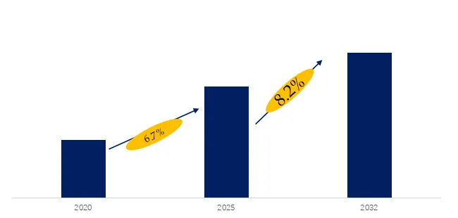
Above data is based on report from QYResearch: Global Non-ferrous Metal Recycling Solutions Market Report 2026-2032 (published in 2025). If you need the latest data, plaese contact QYResearch.


2 Introduction of Major Manufacturers of Non-ferrous Metal Recycling Solutions

Serial Number Company
1 SMS group GmbH
2 Steinert
3 Harmony Enterprises
4 Recco Non Ferro Metals
5 Rubicon
6 Wanless Waste Management
7 WARD
8 Cohen
9 Jansen Recycling Group
10 JLM Metal Recycling & Auto Parts
11 Moffatt Scrap Iron & Metal
12 GLR Advanced Recycling
13 Ferrous Processing & Trading
14 Fortum

Source: Third-party data, QYResearch Research Team

According to a survey by QYResearch’s Leading Enterprise Research Center, global Non-ferrous Metal Recycling Solutions manufacturers include SMS group GmbH, Steinert, Harmony Enterprises, Recco Non Ferro Metals, Rubicon, etc. By 2025, the top five global manufacturers will hold approximately 26% of the market share.


Introduction to Key Companies

Company 1

SMS group GmbH Description
Company Introduction SMS group GmbH is a leading global industrial engineering company specializing in metal processing equipment and technology solutions, with particularly strong capabilities in the steel and non-ferrous metals industries. Through innovative technologies and equipment, the company provides efficient production and processing systems to global clients, helping them optimize production processes and improve product quality. SMS group’s solutions cover multiple areas from metallurgy to automation, committed to driving sustainable development and green production. The company boasts a strong global service network, ensuring client success in various markets.
Product Introduction SMS group GmbH offers advanced non-ferrous metal recycling solutions, dedicated to improving recycling efficiency and quality. Its technologies include efficient smelting, sorting, and refining processes that maximize recovery rates and reduce environmental impact. The company employs innovative equipment and intelligent technologies to ensure the efficient extraction and reuse of non-ferrous metals. SMS group’s recycling systems are suitable for various non-ferrous metals, including aluminum and copper, helping companies achieve resource recycling, reduce production costs, and comply with increasingly stringent environmental standards.

Source: Third-party data, QYResearch Research Team

Company 2

Steinert Description
Company Introduction Steinert is a leading global company specializing in material sorting and recycling technologies, providing innovative solutions for non-ferrous metal recycling, waste treatment, and mineral sorting. The company utilizes advanced magnetic separation, X-ray sorting, and spectroscopy technologies to provide efficient and precise sorting and recycling equipment for clients across various industries. Steinert’s products are widely used in the mining, recycling, and waste management sectors, helping clients improve resource utilization and optimize production processes. The company is committed to promoting sustainable development and developing environmentally friendly and energy-saving technological solutions.
Product Introduction Steiner’s non-ferrous metal recycling solutions utilize advanced material sorting technologies to help clients efficiently recycle non-ferrous metals. Through technologies such as magnetic separation, X-ray sorting, and laser sorting, Steinert’s equipment can accurately extract precious metals such as copper, aluminum, and nickel from waste. These solutions not only improve recycling efficiency but also ensure the extraction of high-quality metals, meeting stringent environmental requirements. Steinert’s systems help clients reduce waste disposal costs and achieve resource recycling, thereby promoting a green economy and sustainable development.

Source: Third-party data, QYResearch Research Team


Company 3

Harmony Enterprises Description
Company Introduction Harmony Enterprises is a company specializing in providing waste treatment and recycling equipment, committed to innovation and sustainable development. The company provides clients with a diverse range of waste compression and recycling solutions, with particular expertise in non-ferrous metal recycling and waste management. Harmony Enterprises helps businesses achieve efficient waste recycling, reduce operating costs, and improve resource utilization through its advanced technologies. The company serves a wide range of industries, including waste treatment, recycling, waste management, and environmental protection, driving global circular economy and environmental protection goals.
Product Introduction Harmony Enterprises’ non-ferrous metal recycling solutions offer efficient waste compression and sorting technologies to help businesses recover precious metals such as aluminum, copper, and steel. Through its innovative waste compression and recycling equipment, Harmony helps customers reduce waste volume and increase metal recovery rates. Its product designs prioritize energy efficiency and environmental protection, ensuring minimal environmental impact during processing. Through intelligent and automated technologies, Harmony Enterprises’ solutions make non-ferrous metal recycling more efficient, economical, and environmentally compliant, helping businesses achieve their sustainability goals.

Source: Third-party data, QYResearch Research Team

3 Non-ferrous Metal Recycling Solutions Industry Chain Analysis

Industry Chain Description
Upstream The upstream of the non-ferrous metal recycling industry chain mainly includes a scrap metal recycling network, dismantling and sorting enterprises, and the collection of social and industrial waste. The recycling network encompasses scrap recycling stations, auto dismantling plants, electronic waste processing companies, and building demolition companies, responsible for collecting waste containing non-ferrous metals such as copper, aluminum, lead, and zinc from scrapped vehicles, waste electronic products, construction waste, and industrial scrap. The upstream segment also involves preliminary manual or mechanical dismantling, sorting, and packaging to remove impurities such as plastics and rubber, providing raw materials for downstream processing. The coverage density, sorting accuracy, and logistics efficiency of the recycling network directly determine the raw material supply capacity of the entire industry chain and are the starting point for industry operation.
Midstream The midstream of the industry chain is the core processing stage of metal recycling, including intelligent sorting, pyrometallurgical or hydrometallurgical processes, refining and purification, and the production of recycled materials. Modern sorting plants employ advanced technologies such as AI visual recognition, X-ray fluorescence spectroscopy, and eddy current separation to accurately separate mixed waste into different categories of pure metal components. Smelting enterprises transform waste metals into standard products such as recycled copper, recycled aluminum, and recycled lead through processes like smelting and electrolysis. Some high-end production lines can also produce high-quality materials such as aerospace-grade recycled aluminum alloys and electronic-grade recycled copper. The technological level of the midstream segment determines the metal recovery rate, product purity, and energy consumption and environmental protection indicators, making it the core of value creation in the industrial chain.
Downstream The downstream of the industrial chain covers various application scenarios for recycled metals and a service system derived from the circular economy. Major users include processing companies in industries such as automobile manufacturing, building materials, electronics, and packaging materials, which use recycled copper and aluminum to produce end products such as parts, profiles, and cables. Driven by dual carbon targets, more and more brands are committing to using green recycled materials, and the downstream market is shifting from price-oriented to low-carbon value-oriented. Furthermore, the downstream has extended to professional services such as recycled metal carbon footprint certification, green supply chain consulting, international waste trade, and futures hedging, forming a complete circular economy industrial ecosystem.

Source: Third-party data, QYResearch Research Team

4 Non-ferrous Metal Recycling Solutions Industry Development Trends, Opportunities, Obstacles and Industry Barriers
Development Trends:

1. The market continues to expand, with a trillion-dollar sector rapidly taking shape. The global metal recycling market is experiencing steady growth. This expansion is mainly due to increasing awareness of the depletion of metal reserves and the continued rise in demand for recycled metals from end-use industries such as automotive, construction, and electronics. Recycling, as a process of dual importance to industry and the environment, is evolving from a peripheral supplement to a mainstream supply model.

2. Green transformation has become a global consensus, with significant regional differences in development paths. Against the backdrop of global carbon reduction, recycled metals have become a key resource for the steel and non-ferrous metals industries. By 2025, 63 countries worldwide had incorporated recycled metal utilization into their carbon neutrality assessment systems. However, there are significant differences between developing and developed countries in terms of resource endowment, policy systems, and technological capabilities. Resource-sufficient countries are actively investing in new technologies, while resource-importing countries face import dependence and the risk of overcapacity. Regional differentiation is reshaping the global industrial landscape.

3. Technological innovation and digitalization are empowering industries to improve quality and efficiency. Intelligent inspection, standardized quality control, and low-carbon process innovation have become common choices for the industry to address challenges. The integration of technologies such as artificial intelligence, machine learning, the Internet of Things, and blockchain is optimizing recycling processes, improving compliance, enhancing inventory management, and increasing decision-making accuracy. Digital tools are driving supply chain transparency, providing strong support for carbon footprint traceability and green certification, and the industry is undergoing a comprehensive upgrade from traditional manual sorting to intelligent precision recycling.

Development Opportunities:

1. Dual-carbon goals drive essential demand for green metals. Driven by the deepening implementation of dual-carbon goals and the rapid development of the new energy industry, the resource security value and low-carbon emission reduction attributes of recycled metals are becoming increasingly prominent. The implementation of EU carbon tariffs and carbon neutrality policies in various countries makes green recycled metals a significant advantage in export trade. Recycling can significantly reduce energy consumption, greenhouse gas emissions, and minimize the extraction of new resources, making it a more sustainable option.

2. Emerging fields expand high-value applications. The application scenarios for recycled metals in emerging fields such as the “new three pillars” (new energy equipment, lithium batteries, and wind power equipment), the low-altitude economy, and robotics are constantly expanding. Strong demand for recycled metals from industries such as automotive, construction, electronics, and packaging confirms their cost-effectiveness and superior performance. Advances in recycling technology have improved the purity of these materials, enabling recycled metals to directly enter high-end manufacturing fields such as aerospace and precision electronics, driving the industry’s transformation from simple “quantity increase” to high-quality “quality improvement.”

3. Asia Pacific becomes the fastest-growing emerging market. Due to accelerating economic growth, the Asia Pacific region is expected to become the world’s largest and fastest-growing metal recycling market. The increasing demand for metals from emerging countries such as India and China is strongly boosting market development in the region. Southeast Asia and South Asia, leveraging their geographical advantages, have become emerging global raw material distribution markets. India imports an average of 1.8 million tons of recycled aluminum raw materials annually, while Thailand’s scrap aluminum exports have surged by 76% year-on-year.

Hindering Factors:

1. International trade barriers are reshaping the global trade landscape. The global recycled metals market is experiencing unprecedented regulatory volatility in 2026. The US has implemented a 10% comprehensive import tariff, the EU is considering restricting scrap exports, and Malaysia has imposed an absolute ban on e-waste imports. These policies are reshaping traditional scrap trade flows, leading to increased compliance costs, blocked arbitrage opportunities, and a highly uncertain international trade environment for market participants. Traditional aluminum scrap trade flows are being completely reshaped.

2. Fluctuations in primary metal prices impact recycling economics. One of the main limiting factors affecting the global recycled metals market is the volatility of raw material metal prices, which leads to fluctuations in recycling operations. When primary metal market prices fall, the economic incentive for recycling decreases, forcing recyclers to reduce processing volumes or lower profit margins. The complex sorting and processing of mixed metals further increases operational difficulty and costs, and regulatory barriers and insufficient recycling infrastructure in some regions exacerbate these challenges.

3. Alloy melting leads to technical bottlenecks in downgraded recycling. While chemically stable metals such as copper can be recycled without loss of quality, steel and aluminum are often alloyed with elements that are difficult to separate, leading to downgraded recycling and quality degradation. Aluminum recycling faces alloy-related limitations, requiring precise separation by alloy type to maintain material quality. Without fine sorting, recycled output is often downgraded, limiting its usability and market value. These thermodynamic and technological constraints are compounded by other structural limitations.

Barriers:

1. Capital Scale and Global Network Deployment Barriers: Advanced sorting and traceability systems require upfront investment, but in the absence of a clear business model, stable demand, or effective incentives, these investments struggle to yield reasonable returns. In uncertain markets, companies are reluctant to shift resources away from established production methods. International giants are accelerating mergers and acquisitions to compete for high-quality raw material resources, leading to a restructuring of the global recycled metal raw material trade landscape. The density of the recycling network directly impacts raw material acquisition capabilities, creating natural capital and scale barriers.

2. Technological R&D and Sorting Capability Barriers: The application level of technologies such as intelligent sorting and low-energy smelting directly determines metal recovery rates and product quality stability. Even if secondary processes are technically feasible, demand structures often still reinforce the use of virgin materials. The application of recycled materials is limited by insufficient buyer interest, high dismantling costs, and unstable supply quality. Virgin materials are typically cheaper, of guaranteed quality, and supported by long-term procurement practices, limiting the market coverage of recycled alternatives.

3. Environmental Compliance and Policy Regulatory Barriers: Governments worldwide have implemented strict regulations to curb illegal mining and the exploitation of metal reserves. While these measures have positively impacted industry growth, they have also significantly raised compliance thresholds. The EU’s Basel Convention amendments have imposed strict controls on the trade of electronic waste resources, and Malaysia has extremely stringent requirements for the SIRIM purity of imported waste. High compliance costs exclude non-compliant companies, and only those with robust environmental systems and compliance capabilities can establish themselves in the international market.


The report provides a detailed analysis of the market size, growth potential, and key trends for each segment. Through detailed analysis, industry players can identify profit opportunities, develop strategies for specific customer segments, and allocate resources effectively.

The Non-ferrous Metal Recycling Solutions market is segmented as below:
By Company
SMS group GmbH
Steinert
Harmony Enterprises
Recco Non Ferro Metals
Rubicon
Wanless Waste Management
WARD
Cohen
Jansen Recycling Group
JLM Metal Recycling & Auto Parts
Moffatt Scrap Iron & Metal
GLR Advanced Recycling
Ferrous Processing & Trading
Fortum
BIG – Brannon Industrial Group

Segment by Type
Electrolytic Deposition
Precipitation
Non-ferrous Metal Sensor

Segment by Application
Steel
Iron
Aluminum
Alloy
Others

Each chapter of the report provides detailed information for readers to further understand the Non-ferrous Metal Recycling Solutions market:

Chapter 1: Introduces the report scope of the Non-ferrous Metal Recycling Solutions report, global total market size (valve, volume and price). This chapter also provides the market dynamics, latest developments of the market, the driving factors and restrictive factors of the market, the challenges and risks faced by manufacturers in the industry, and the analysis of relevant policies in the industry. (2021-2032)
Chapter 2: Detailed analysis of Non-ferrous Metal Recycling Solutions manufacturers competitive landscape, price, sales and revenue market share, latest development plan, merger, and acquisition information, etc. (2021-2026)
Chapter 3: Provides the analysis of various Non-ferrous Metal Recycling Solutions market segments by Type, covering the market size and development potential of each market segment, to help readers find the blue ocean market in different market segments. (2021-2032)
Chapter 4: Provides the analysis of various market segments by Application, covering the market size and development potential of each market segment, to help readers find the blue ocean market in different downstream markets.(2021-2032)
Chapter 5: Sales, revenue of Non-ferrous Metal Recycling Solutions in regional level. It provides a quantitative analysis of the market size and development potential of each region and introduces the market development, future development prospects, market space, and market size of each country in the world..(2021-2032)
Chapter 6: Sales, revenue of Non-ferrous Metal Recycling Solutions in country level. It provides sigmate data by Type, and by Application for each country/region.(2021-2032)
Chapter 7: Provides profiles of key players, introducing the basic situation of the main companies in the market in detail, including product sales, revenue, price, gross margin, product introduction, recent development, etc. (2021-2026)
Chapter 8: Analysis of industrial chain, including the upstream and downstream of the industry.
Chapter 9: Conclusion.

Benefits of purchasing QYResearch report:
Competitive Analysis: QYResearch provides in-depth Non-ferrous Metal Recycling Solutions competitive analysis, including information on key company profiles, new entrants, acquisitions, mergers, large market shear, opportunities, and challenges. These analyses provide clients with a comprehensive understanding of market conditions and competitive dynamics, enabling them to develop effective market strategies and maintain their competitive edge.

Industry Analysis: QYResearch provides Non-ferrous Metal Recycling Solutions comprehensive industry data and trend analysis, including raw material analysis, market application analysis, product type analysis, market demand analysis, market supply analysis, downstream market analysis, and supply chain analysis.

and trend analysis. These analyses help clients understand the direction of industry development and make informed business decisions.

Market Size: QYResearch provides Non-ferrous Metal Recycling Solutions market size analysis, including capacity, production, sales, production value, price, cost, and profit analysis. This data helps clients understand market size and development potential, and is an important reference for business development.

Other relevant reports of QYResearch:
Global Non-ferrous Metal Recycling Solutions Sales Market Report, Competitive Analysis and Regional Opportunities 2025-2031
Global Non-ferrous Metal Recycling Solutions Market Outlook, In‑Depth Analysis & Forecast to 2031
Global Non-ferrous Metal Recycling Solutions Market Research Report 2025

About Us:
QYResearch founded in California, USA in 2007, which is a leading global market research and consulting company. Our primary business include market research reports, custom reports, commissioned research, IPO consultancy, business plans, etc. With over 19 years of experience and a dedicated research team, we are well placed to provide useful information and data for your business, and we have established offices in 7 countries (include United States, Germany, Switzerland, Japan, Korea, China and India) and business partners in over 30 countries. We have provided industrial information services to more than 60,000 companies in over the world.

Contact Us:
If you have any queries regarding this report or if you would like further information, please contact us:
QY Research Inc.
Add: 17890 Castleton Street Suite 369 City of Industry CA 91748 United States
EN: https://www.qyresearch.com
Email: global@qyresearch.com
Tel: 001-626-842-1666(US)
JP: https://www.qyresearch.co.jp

カテゴリー: 未分類 | 投稿者huangsisi 12:54 | コメントをどうぞ